TM 5-3895-382-24
10.
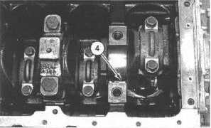
Put the oil strainer in position on the engine and install
bolts (4) and bolt ().
11.
Put the oil pressure relief valve in position on the engine
and install two bolts (1) and bolt (2).
End By:
a.
Install the engine oil pan. Refer to Disassembly
and Assembly, "Engine Oil Pan - Remove and
Install".
Crankshaft Main Bearings - Remove
SMCS Code: 1203-011
Removal Procedure
Table 38
Required Tools
Tool
Part
Number
Part Description
Qty
A
9U-6282
Torque Wrench Extension
1
Start By:
a.
Remove the engine oil relief valve and the strainer
assembly. Refer to Disassembly and Assembly,
"Engine Oil Relief Valve - Remove and Install".
NOTICE
Keep all parts clean from contaminants.
Contaminants may cause rapid wear and shortened
component life.
NOTE:
Remove the following components from the
engine in order to remove the rear main bearing
with the crankshaft in position: flywheel, flywheel
housing, rear oil seal housing and bridge
assembly.
NOTE:
Tool (A) must be used in order to remove the front
main bearing cap with the front housing and the
engine oil pump in place. If Tool (A) is not
available, removal of the front cover and the
engine oil pump will be necessary. The engine oil
pump is attached to the front main bearing cap.
Removal of the bolts is not possible with a socket.
Refer to Disassembly and Assembly, "Engine Oil
Pump -Remove".
1.
Remove all necessary components in order to gain
access to the specific main bearing cap.
2.
Make sure that the main bearing cap is marked for the
location and direction for installation. The main
bearings and the main bearing caps must be installed in
the same location.
Illustration 204
3.
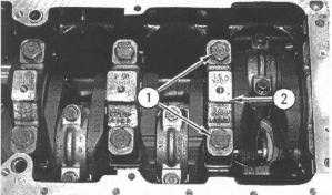
Remove two bolts (1) and main bearing cap (2).
Illustration 205
4.
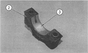
Remove lower main bearing (3) from main bearing cap
(2). Keep the respective main bearing and the main
bearing cap together for proper installation.
Illustration 206
7-81


