TM 5-3895-382-24
b.
Type 2 and 7BJ Engines
Calculate the difference between the lowest
measurement and the highest measurement of the
four locations. This difference must not be greater
than 0.03 mm (0.001 inch) for every 25 mm (1.0 inch)
of the radius of the flywheel. The radius of the
flywheel is measured from the axis of the crankshaft
to the contact point of the dial indicator.
Outside Diameter Check
NOTE:
The flywheel housing may require removal in
order to perform this runout check.
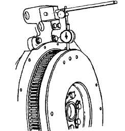
Illustration 102
Tooling setup for measuring the outside diameter runout of the
flywheel.
1.
Mount the magnetic base of the dial indicator group to
the flywheel housing or the engine block Position the
contact of the dial indicator on the top of the flywheel in
Illustration 102, as shown. Set the pointer of the dial
indicator to 0.00 mm (0.000 inch).
2.
Turn the flywheel. Read the dial indicator for every 90
degrees.
3.
Calculate
the
difference
between
the
lowest
measurement and the highest measurement of the four
locations. This difference must not be greater than 0.30
mm (0.012 inch). This dimension is the maximum
permissible distance for the outside diameter runout of
the flywheel.
Electrical System
SMCS Code: 1400
Test Tools For The Electrical
System
Most of the tests of the electrical system can be done on the
engine. if the test shows a defect in a component, remove the
component for more testing.
Before the electrical system is tested, the following conditions
should exist:
The wiring insulation must be in good condition.
The wire and cable connections must be clean and tight.
The battery must be fully charged.
Table 28
Tools Needed
4C-4911
Battery Load Tester
1
8T-0900
Ammeter
1
6V-7070
Digital Multimeter
1
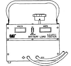
4C-4911 Battery Load Tester
Illustration 103
4C-4911 Battery Load Tester.
6-98