TM 5-3895-382-24
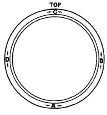
Illustration 98
Locations for measuring the face runout of the flywheel housing.
(A) Bottom
(B) Right Side
(C) Top
(D) Left side
3.
Set the dial indicator to 0.0 mm (0.00 inch) at location
(A). Turn the crankshaft in order to measure the face
runout at locations (B), (C), and (D).
4.
Maximum face runout.
NOTE:
For a complete description of Type 1 and Type 2
engines, refer to the Systems Operation, Testing
and Adjusting Module, "Engine Design" for more
information.
a.
Type 1 and 9RM Engines
Calculate
the
difference
between
the
lowest
measurement and the highest measurement of the
four locations. This difference must not be greater
than 0.20 mm (0.008 inch). This dimension is the
maximum permissible face runout of the flywheel
housing.
b.
Type 2 and 7BJ Engines
Calculate
the
difference
between
the
lowest
measurement and the highest measurement of the
four locations. This difference must not be greater
than the limit that is given in the following table. This
difference is the maximum permissible face runout of
the flywheel housing.
Table 27
Bore Of The
Housing Flange
Maximum Permissible
Face Runout
362 mm (14.25 inch)
0.23 mm (0.009 inch)
410 mm (16.14 inch)
0.25 mm (0.010 inch)
448 mm (17.64 inch)
0.28 mm (0.011 inch)
511 mm (20.12 inch)
0.30 mm (0.012 inch)
584 mm (22.99 inch)
0.36 mm (0.014 inch)
648 mm (25.51 inch)
0.41 mm (0.016 inch)
787 mm (30.98 inch)
0.48 mm (0.019 inch)
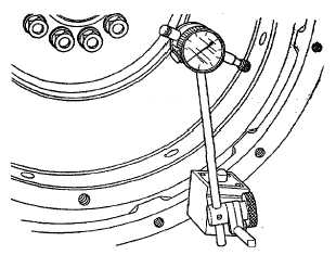
Bore Runout Check
Illustration 99
Bore runout check.
6-96