TM 5-3895-382-24
2.
Measure the depth of the inlet valve and the exhaust
valve below the cylinder head face. Use the gauge
body (2) and the dial indicator (1) in order to measure
the depth.
Refer to Specifications, "Cylinder Head Valve for the
minimum, the maximum, and the service wear limits for
the valve depth below the cylinder head face. The
minimum and the maximum limits are dimensions for a
new engine.
Service wear occurs on an engine which has been in
operation. If the valve depth below the cylinder head
face on a used engine exceeds the specification for
service wear, the following Items must be replaced:
valves
valve inserts
If the valve depth below the cylinder head face on a
used engine exceeds the specification for service wear,
the cylinder head may also need to be replaced.
Testing The Valve Guides
Perform this test in order to determine if a valve guide should
be replaced.
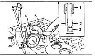
Illustration 71
Measure The Radial Movement Of The Valve In The Valve Guide.
(1) Valve guide
(2) Radial movement o the valve in the valve guide
(3) Valve stem
(4) Dial indicator
(5) When the valve head is lifted, the edge of the valve head is the
following value: 15.0 mm (0.60 inch)
1.
Place a new valve in the valve guide.
2.
Place a dial indicator with a magnetic base on the face
of the cylinder head.
3.
Lift the edge of the valve head to a distance of 15.0 mm
(0.60 inch).
4.
Move the valve in a radial direction away from the dial
indicator. Make sure that the valve moves away from
the dial indicator as far as possible. Position the contact
point of the dial indicator on the edge of the valve head.
Set the position of the needle of the dial indicator to
zero.
5.
Move the valve in a radial direction toward the dial
indicator as far as possible. Note the distance of
movement which is indicated on the dial indicator. If the
distance is greater than the maximum clearance of the
valve in the valve guide, replace the valve guide. The
maximum clearance is given in Specifications, "Cylinder
Head Valves".
Replacing Valve Guides and Valve Inserts
Table 15
Tools Needed
Valve Seat Cuter and
157-3720
Guide Reamer
1
NOTE:
The valve seat cutter of the 157-3720 Valve Seat
Cutter and Guide Reamer has two cutting sides.
One side is for cutting the valve seat in the valve
insert for naturally aspirated engines which have
46 degree valve seats. The other side of the
cutter is for cutting the valve seat in the valve
insert for turbocharged engines which have 31
degree valve seats.
When new valve guides are installed, new valves and new
valve seat inserts must be installed. Valve guides and valve
seat inserts are supplied as a partially finished part. The
unfinished valve guides and unfinished valve seat inserts are
installed in the cylinder head. Then, the valve guides and
valve inserts are cut and reamed in one operation with special
tooling. This procedure ensures the concentricity of the valve
seat to the valve guide in order to create a seal that is gas tight
NOTE:
All lubricant must be removed from the outside of
the inlet and exhaust valve guides before the
valve seal is installed.
Perform the following procedure in order to correctly adjust
new valve guides and valve insets:
1.
Remove the original valve guide and the original valve
seat insert. Install a new valve guide and a new valve
seat insert. Refer to the Disassembly and Assembly
manual for removal and installation procedures for valve
guides and valve inserts.
NOTE:
Do not cut the valve seat before the valve guide is
installed.
6-75


