TM 5-3895-382-24
2.
Machine the recess in the cylinder head for the valve
seat insert. Refer to the dimensions that are given in
the Specifications manual. Use the bore of the new
valve guide as a guide.
Remove all debris. Thoroughly clean the recess for the
valve seat insert.
3.
Ensure that the valve seat insert does not protrude
above the bottom face of the cylinder head. If the valve
seat insert protrudes above the bottom face of the
cylinder head, the back of the valve seat insert must be
machined. Refer to the Specifications manual for
dimensions of the valve seat insert.
4.
Press the valve seat insert into the recess of the
cylinder head for the valve sea insert. Use a hydraulic
press or a driver in order to install the valve seat insert.
Use the bore of the new valve guide as a guide. Refer
to the Disassembly and Assembly manual for additional
information regarding tools. Ensure that the bottom of
the valve seat insert fully contacts the bottom of the
recess in the cylinder head.
5.
Cut the valve seat with the valve seat cuter. Refer to
the Specifications manual for the correct angles and
dimensions for the valve seats and depth of the valve
head. Ensure that the depth of the valve head below
the face of the cylinder head is within the tolerance.
Testing The Wastegate
If the valve of the wastegate does not operate at the correct
pressure, the performance of the engine will be adversely
affected. If the valve opens at a pressure that is too low, the
following items will occur: black exhaust smoke and loss of
power at lower engine rpm. If the valve opens at a pressure
that is too high, pressures in the engine cylinders will be too
high. Cylinder pressures that are too high will cause the
following items to occur failure of the cylinder head gasket and
damage to the bearings and the pistons.
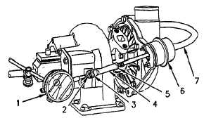
Illustration 72
The wastegate is mounted on the turbocharger.
(1) Dial indicator
(2) Clip
(3) Pin
(4) Actuator rod
(5) Locknut
(6) Actuator
(7) Line for the boost sensor
1.
Disconnect the line for the boost sensor (7) at the
actuator (6). Connect an air supply to the actuator. The
pressure of the air supply must not exceed 207 kPa
(30 psi). The pressure of the air supply must be
measured by a gauge which is capable of measuring
pressures to the nearest 0.7 kPa (0.1 psi). The
pressure of the air supply must be capable of
adjustment to the nearest 0.7 kPa (0.1 psi).
2.
Place a magnetic base on the turbocharger. Position
the contact of the dial indicator (1) on the end of the
actuator rod (4). Set the pointer of the dial indicator to
zero.
3.
Slowly increase the air pressure. Determine the air
pressure which is necessary in order to move the
actuator rod. The actuator rod should move a distance
of the following value: 1.00 mm (0.039 inch).
Purge the air pressure. Ensure that the needle of the
dial indicator moves to zero when the pressure from the
air supply is purged in order to repeat the test.
Repeat this step one or more times in order to ensure
that an accurate air pressure is obtained for opening the
valve of the wastegate. Compare the opening pressure
of the valve of the wastegate in the following table with
the measured pressure.
6-76


