TM 5-3895-382-24
Fuel Injection Pump (Stanadyne)
Illustration 6
Fuel Injection Pump (Stanadyne).
Hub nut (not shown)
NOTE: Do not release the hub nut from the fuel injection
pump. The fuel pump hub is positioned to the
pump shaft in order to ensure that the fuel pump
is in the correct position for timing. If the hub is
removed, the hub will need to be accurately
positioned
to
the
pump
shaft.
Accurate
positioning requires the use of special equipment
by a Caterpillar Dealer.
(1)
Electrical connection for the stop solenoid
(2)
Tighten the fitting for the fuel return line
connection to the following torque: .................. 5 to 6 Nm
(44 to 53 lb-in)
(3)
Tighten the adjustment screw for the low idle to
the following torque: ........................................4 to 4.5 Nm
(35 to 40 lb-in)
(4)
Tighten the adjustment screw for the high idle
to the following torque: ...................................4 to 4.5 Nm
(35 to 40 lb-in)
(5)
Tighten the flange nuts to the following
torque: ........................................................28 Nm (21 lb-ft)
(6)
Tighten the nut for the end cap t the following
torque: ........................................................22 Nm (16 lb-ft)
(7)
Tighten the fittings for the fuel discharge to the
following torque:.......................................70.5 to 81.4 Nm
(52 to 60 lb-ft)
(8) Tighten the nuts for the fuel line to the following
torque: ....................................................................22 Nm (16 lb-ft)
(9) Adjustment screw for advance timing
NOTE:
The fuel injection pump must be installed after the
following function has been performed: The
engine must be set to he top center compression
position on number 1 cylinder.
Fuel Injection Nozzles
SMCS Code: 1254
Type 1 Engines and 9RM Engines
NOTE: For a complete description of Type 1 and Type 2
engines, refer to the Specifications Module,
"Engine Design" for more information.
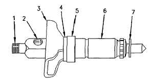
Illustration 7
injector nozzle
(1) Connection for the union nut of the supply line
(2) Threaded hole for the banjo bolt of the leak off line
(3) Clamp
(4) Seal
(5) Spacer
(6) Fuel injector assembly
(7) Seat washer
(1)
Tighten the union nut of the high pressure fuel
line (not shown) to me following
torque: .....................................................18 Nm (13.3 lb-ft)
(2)
Tighten the banjo bolts of the leak off tubing
(not shown) to the following torque: .....................9.5 Nm
(84 lb-in)
(3)
Tighten the flange bolts (not shown) for the
clamp to the following torque: ..................12 Nm (9 lb-ft)
5-8


