TM 5-3895-382-24
Compression Ratio ..............................................................17.25:1
Number of cylinders ......................................................................... 4
Arrangement of cylinders ........................................................in-line
Firing Order .......................................................................... 1,3, 4, 2
Valve Lash
Inlet valve ..........................................0.20 mm (.008 inch)
Exhaust valve ...................................0.45 mm (.018 inch)
When the crankshaft is viewed from the front of the engine the
crankshaft rotates in the following
direction: ........................................................................... Clockwise
When the camshaft is viewed from the front of the engine the
camshaft rotates in the following
direction: ........................................................................... Clockwise
NOTE: The front end of the engine is opposite the
flywheel end. The left side and the right side of
the engine are viewed from the flywheel end. The
No. 1 cylinder is the front cylinder.
Fuel Injection Pump
SMCS Code: 1251
Type 1 Engines and 9RM Engines
NOTE: For a complete description of Type 1 and Type 2
engines, refer to the Specifications Module,
"Engine Design" for more information.
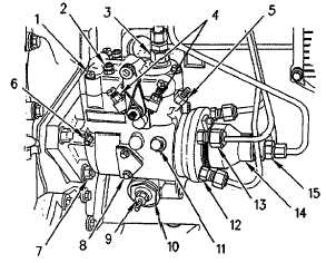
Fuel Injection Pump (Bosch and Stanadyne)
Illustration 3
Fuel Injection Pump (Typical Example).
(1)
Tighten the cover bolts to the following
torque: .................................................................. 4 to 5 Nm
(35 to 45 lb-in)
(2)
Terminals of the solenoid
(3)
Tighten the nut for the fuel return line
connection to the following torque:................... 5 to 6 Nm
(45 to 53 lb-in)
(4)
Tighten the locking nuts for the adjustment
screws of the high idle and the low idle to the
following torque: ..............................................4 to 4.5 Nm
(35 to 40 lb-in)
(5)
Tighten the nut for the torque screw to the
following torque: ..............................................3 to 3.5 Nm
(26 to 30 lb-in)
(6)
Tighten the nut of the pivot shaft to the following
torque: ...............................................................2.3 to 3 Nm
(20 to 25 lb-in)
(7)
Tighten the flange nuts to the following
torque:.........................................................28 Nm (21 lb-ft)
(8)
Tighten the screw for the cover of the timing line
to the following torque: ................................1.5 to 2.5 Nm
(13 to 21 lb-in)
(9)
Tighten the locking nut of the adjustment screw
for the timing advance to the following
torque: ............................................................5.6 to 6.5 Nm
(50 to 60 lb-in)
(10)
Tighten the plug for the piston hole to the
following torque: ......................................24.3 to 30.0 Nm
(18 to 22 lb-ft
5-5