
TM 5-3895-379-23-2
0267
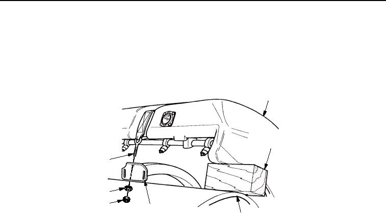
INSTALLATION - Continued
3.
Lift water spray tank (Figure 8, Item 2) and remove wood block (Figure 8, Item 3).
4.
Lower water spray tank (Figure 8, Item 2) on bumper assembly (Figure 8, Item 5).
5.
Install two straps (Figure 8, Item 1) in bumper assembly (Figure 8, Item 5) with two washers (Figure 8, Item 7)
and nuts (Figure 8, Item 6). Tighten nuts until strap tension is snug.
2
3
1
7
6
5
4
M0236SWR
Figure 8. Water Spray Pipe Assembly Installation.
6.
Fill water spray system and check for leaks (TM 5-3895-379-10).
END OF TASK
03/15/2011Rel(1.8)root(maintwp)wpno(M00205)