
TM 5-3895-379-23-2
0268
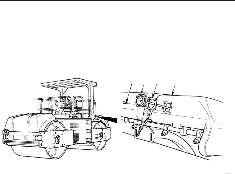
REMOVAL
NOTE
Front and rear water level gauges are replaced the same way. Rear water level gauge
is shown.
Note position of gauge face to aid in installation.
Remove four screws (Figure 1, Item 1), water level gauge (Figure 1, Item 2), and gasket (Figure 1, Item 3)
from water tank (Figure 1, Item 4). Discard gasket if damaged.
1
2
3
4
M0239SWR
Figure 1. Water Level Gauge Removal.
END OF TASK
03/15/2011Rel(1.8)root(maintwp)wpno(M00206)