
TM 5-3895-379-23-2
0267
CLEANING AND INSPECTION - Continued
3.
Check cap and clamp for cracks and wear on locking parts.
4.
Check screen for crushing, corrosion, or tears.
5.
Check seal for cracks, tears, or other signs of deterioration.
6.
Check nozzle for clogging, corrosion, or excessive wear.
7.
Replace all damaged parts.
END OF TASK
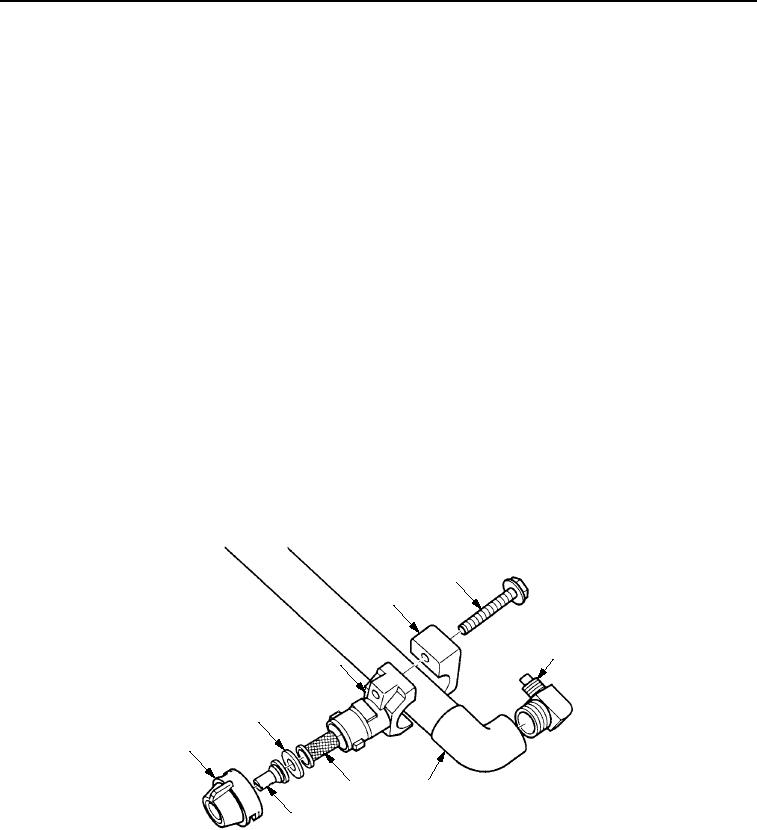
ASSEMBLY
1.
Apply sealing compound to threads and install two elbows (Figure 5, Item 3) in water spray pipe assembly
(Figure 5, Item 4).
2.
Install clamp (Figure 5, Item 1) in water spray pipe assembly (Figure 5, Item 4) with two screws
(Figure 5, Item 2).
3.
Install nozzle (Figure 5, Item 6), seal (Figure 5, Item 8), and screen (Figure 5, Item 5) in cap
(Figure 5, Item 7).
CAUTION
Failure to ensure that cap is securely snapped into locked position will result in possible loss
of nozzle components when water spray system is operated.
4.
Install cap (Figure 5, Item 7) on clamp (Figure 5, Item 1) and turn clamp clockwise until clamp snaps into locked
position.
2
1
3
1
8
7
5
4
6
M0233SWR
Figure 5.
Water Spray Pipe Assembly.
5.
Repeat Steps (2) through (4) for remaining clamps as required.
END OF TASK
03/15/2011Rel(1.8)root(maintwp)wpno(M00205)