
TM 5-3895-379-23-2
0261
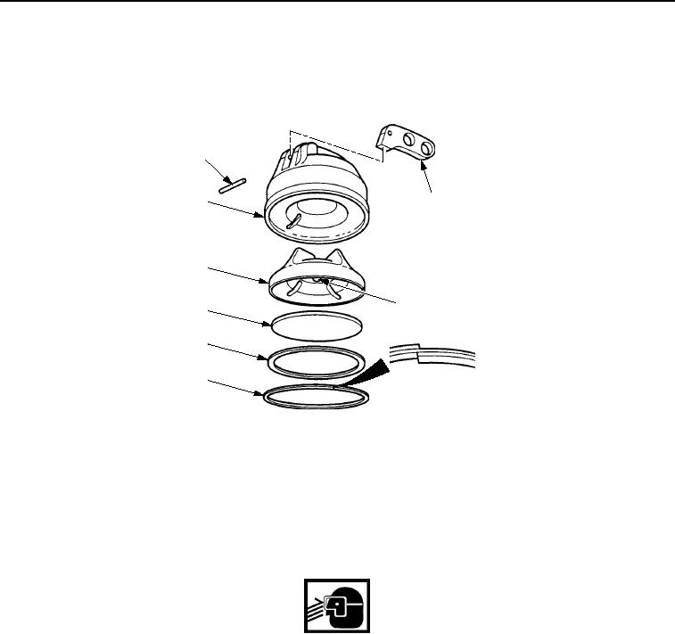
INSPECTION
Check cap (Figure 4, Item 7) and cover (Figure 4, Item 8) for nicks, cracks, dents, and stripped threads. Replace
all damaged parts.
1
2
8
7
3
6
5
4
M1146SWR
Figure 4.
Hydraulic Oil Cap Assembly Cleaning and Inspection.
END OF TASK
INSTALLATION
1.
Install lever (Figure 5, Item 2) on cover (Figure 5, Item 8) with pin (Figure 5, Item 1).
WARNING
Retaining ring is under spring tension to avoid injury, wear eye protection and use caution
when installing.
2.
Install ball (Figure 5, Item 3), cap (Figure 5, Item 7), and retaining ring (Figure 5, Item 4) in cover
(Figure 5, Item 8).
3.
Install pressure plate (Figure 5, Item 6) and new gasket (Figure 5, Item 5) in cover (Figure 5, Item 8).
03/15/2011Rel(1.8)root(maintwp)wpno(M00199)