
TM 5-3895-379-23-2
FIELD MAINTENANCE
VIBRATORY BEARING RESERVOIR SERVICE
INITIAL SETUP:
References (cont.)
Tools and Special Tools
Tool Kit, General Mechanic's: Automotive
Volume 1, WP 0071
(WP 0289, Table 1, Item 39)
Volume 1, WP 0073
Pan, Drain, 5 Gal Cap.
(WP 0289, Table 1, Item 23)
Equipment Condition
Engine on. (TM 5-3895-379-10)
Materials/Parts
Lubricating Oil, Gear
(WP 0288, Table 1, Item 32, 33, 34)
Rag, Wiping (WP 0288, Table 1, Item 60)
Personnel Required
Construction Equipment Repairer 91L
References
TM 5-3895-379-23P, Figure 131
DRAIN
NOTE
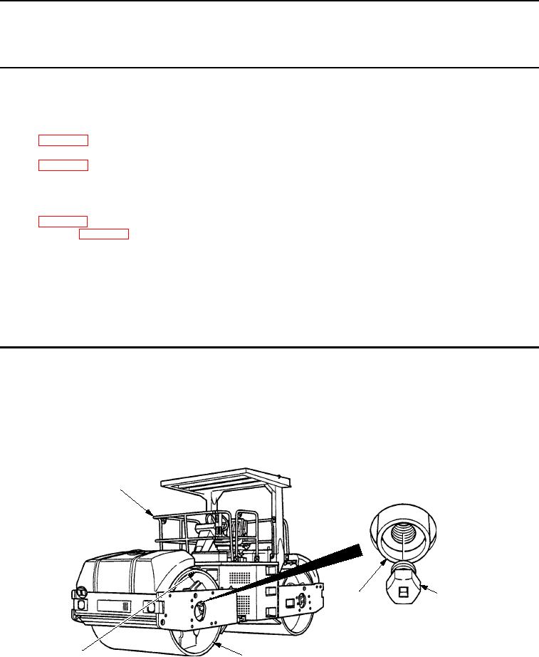
Front and rear vibratory bearing reservoir is serviced the same way. Front vibratory bearing
reservoir is shown.
1.
Move roller (Figure 1, Item 1) until bar (Figure 1, Item 5) is at top of drum (Figure 1, Item 4).
1
2
3
M0190SWR
5
4
Figure 1.
Vibratory Bearing Reservoir Drain.
2.
Turn engine off (TM 5-3895-379-10).
03/15/2011Rel(1.8)root(maintwp)wpno(M00200)