
TM 5-3895-379-23-2
0237
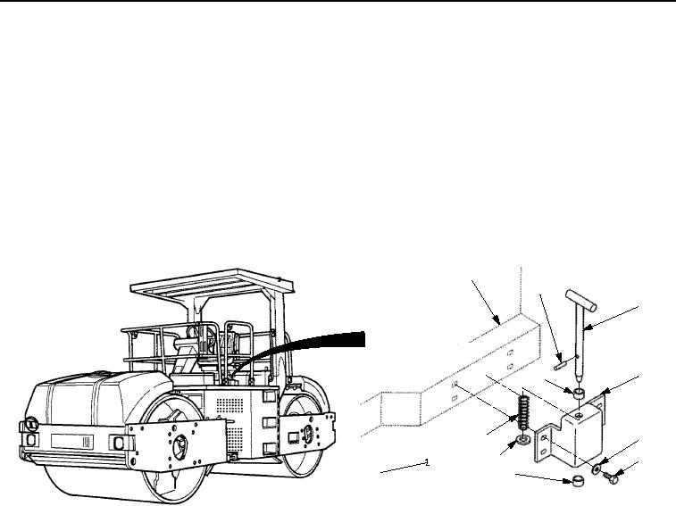
INSTALLATION
1.
Install two bearings (Figure 2, Item 4) on rotate lock assembly plate (Figure 2, Item 5).
2.
Install spring (Figure 2, Item 8), washer (Figure 2, Item 9), and pin (Figure 2, Item 3) in rotate lock assembly
plate (Figure 2, Item 5).
3.
Compress washer (Figure 2, Item 9) and spring (Figure 2, Item 8) and install spring pin (Figure 2, Item 2) in
pin (Figure 2, Item 3).
4.
Install rotate lock assembly (Figure 2, Item 5) on operator station (Figure 2, Item 1) with four washers
(Figure 2, Item 6) and screws (Figure 2, Item 7). Do not tighten screws.
5.
Align pin (Figure 2, Item 3) with hole in operator platform (Figure 2, Item 10) and tighten screws to 33-47 lb-ft
(45-64 Nm).
1
2
3
5
4
8
6
9
7
4
10
M1258SWR
Figure 2.
Rotate Lock Installation.
END OF TASK
FOLLOW-ON MAINTENANCE
Remove chocks. (TM 5-3895-379-10)
END OF TASK
END OF WORK PACKAGE
03/15/2011Rel(1.8)root(maintwp)wpno(M00175)