
TM 5-3895-379-23-2
0229
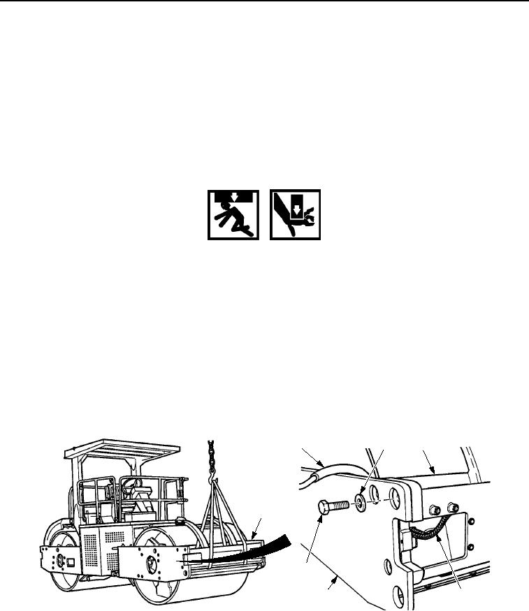
REMOVAL
NOTE
Front and rear supports (bumpers) are replaced the same way. Rear bumper is shown.
Remove electrical tiedown straps as necessary.
Front side down, rear side similar.
1.
Pull wiring harness (Figure 1, Item 1) though hole in backside of bumper assembly (Figure 1, Item 3) and
position in a safe area.
WARNING
Use caution when handling heavy parts. Provide adequate support and use assistance during
procedure. Ensure that any lifting device used is in good condition and of suitable load
capacity. Keep clear of heavy parts supported only by lifting device. Failure to follow this
warning may cause injury or death.
NOTE
Bumper assembly weighs 625 lb (283 kg).
2.
Attach a lifting device to bumper assembly (Figure 1, Item 3).
3.
Remove six screws (Figure 1, Item 5) and washers (Figure 1, Item 2) from bumper assembly
(Figure 1, Item 3).
4.
Operate lifting device while assistant guides bumper assembly (Figure 1, Item 3) away from yoke assembly
(Figure 1, Item 4).
2
1
3
3
5
4
1
M0725SWR
Figure 1. Front and Rear Support (Bumpers) Removal.
END OF TASK
03/15/2011Rel(1.8)root(maintwp)wpno(M00167)