
TM 5-3895-379-23-1
0217
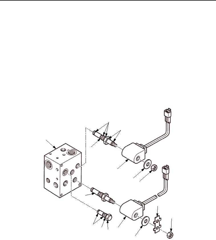
ASSEMBLY
1.
Install two new O-rings (Figure 2, Item 12) and new back-up O-rings (Figure 2, Item 11) to check valve
(Figure 2, Item 10).
2.
Install three new O-rings (Figure 2, Item 2) and two new back-up O-rings (Figure 2, Item 3) to shift valve
cartridge (Figure 2, Item 4) and brake valve cartridge (Figure 2, Item 13).
3.
Install shift valve cartridge (Figure 2, Item 4), brake valve cartridge (Figure 2, Item 13), and check valve
(Figure 2, Item 10) from manifold (Figure 2, Item 1).
4.
Install brake coil (Figure 2, Item 9) from brake valve cartridge (Figure 2, Item 13).
5.
Install shift coil (Figure 2, Item 5) from shift valve cartridge (Figure 2, Item 4).
6.
Install lock (Figure 2, Item 8) and two washers (Figure 2, Item 6) to shift coil (Figure 2, Item 5) and brake coil
(Figure 2, Item 9).
7.
Install nut (Figure 2, Item 7) from shift coil (Figure 2, Item 5) and nut (Figure 2, Item 7) from brake coil
(Figure 2, Item 9). Tighten to 48-70 lb-ft (65-94 Nm).
8.
Bend tabs up on lock (Figure 2, Item 8).
2
3
1
4
5
6
7
13
8
7
12
9
11
10
6
M1155SWR
Figure 2. Brake Control Valve Assembly.
END OF TASK
03/15/2011Rel(1.8)root(maintwp)wpno(M00155)