
TM 5-3895-379-23-1
0216
INSTALLATION - Continued
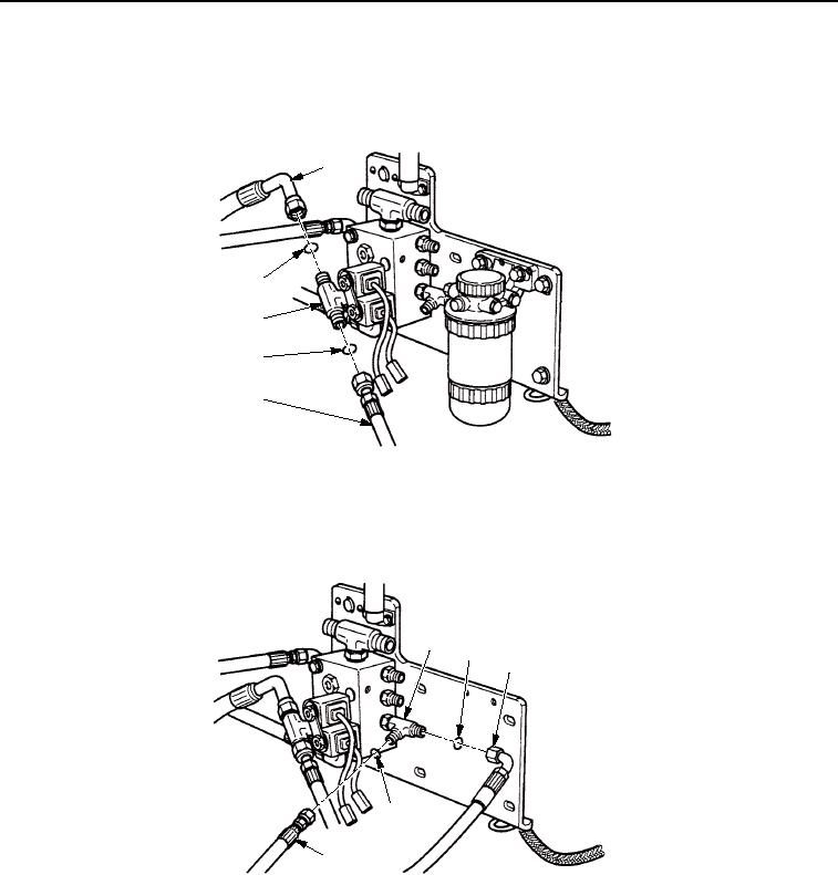
15.
Install two new O-rings (Figure 13, Item 3) and hoses (Figure 13, Items 1 and 2) on swivel tee
(Figure 13, Item 4).
1
3
4
3
2
M0410SWR
Figure 13. Brake Control Valve Installation.
16.
Install two O-rings (Figure 14, Item 2) and hoses (Figure 14, Items 3 and 4) on seal tee (Figure 14, Item 1).
FUEL/WATER SEPARATOR
SHOWN REMOVED
FOR CLARITY
1
2
3
2
4
M0411SWR
Figure 14. Brake Control Valve Installation.
03/15/2011Rel(1.8)root(maintwp)wpno(M00154)