
TM 5-3895-379-23-1
0216
REMOVAL - Continued
4.
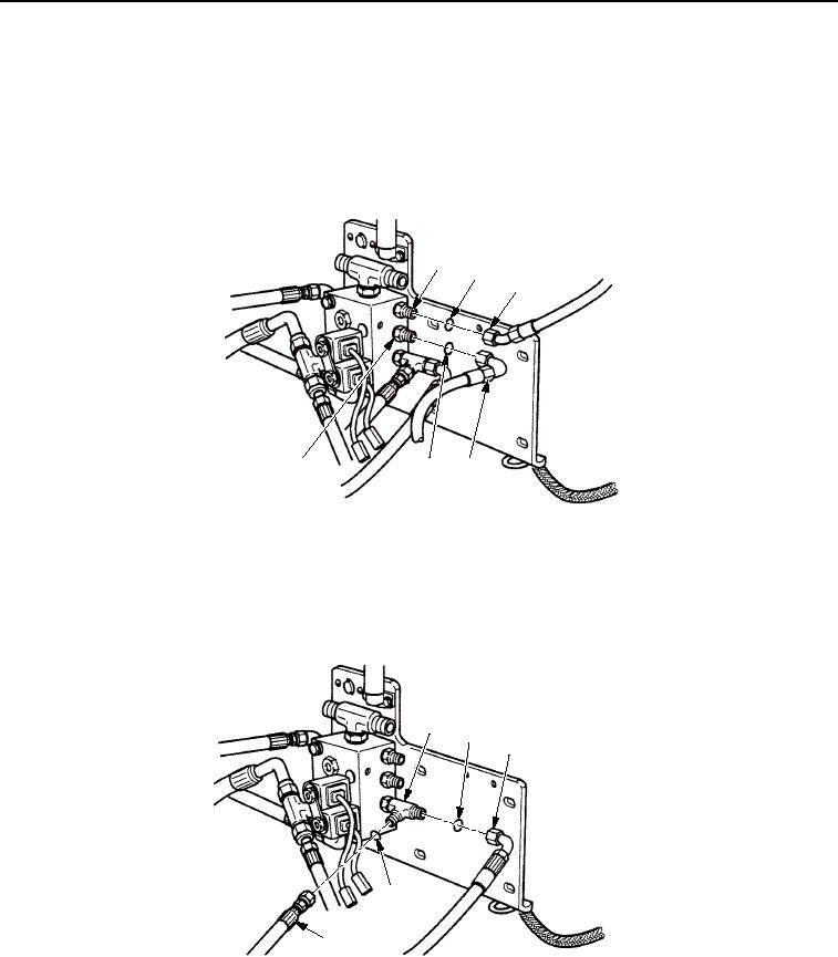
Remove hose (Figure 2, Item 3) and O-ring (Figure 2, Item 2) from straight adapter (Figure 2, Item 1). Discard
O-ring.
5.
Remove hose (Figure 2, Item 4) and O-ring (Figure 2, Item 5) from straight adapter (Figure 2, Item 6). Discard
O-ring.
FUEL/WATER SEPARATOR
SHOWN REMOVED
FOR CLARITY
1
2
3
6
5
4
M0400SWR
Figure 2. Brake Control Valve Removal.
6.
Remove hoses (Figure 3, Items 3 and 4) and O-rings (Figure 3, Item 2) from seal tee (Figure 3, Item 1). Discard
O-rings.
FUEL/WATER SEPARATOR
SHOWN REMOVED
FOR CLARITY
1
2
3
2
4
M0401SWR
Figure 3. Brake Control Valve Removal.
03/15/2011Rel(1.8)root(maintwp)wpno(M00154)