
TM 5-3895-379-23-1
0193
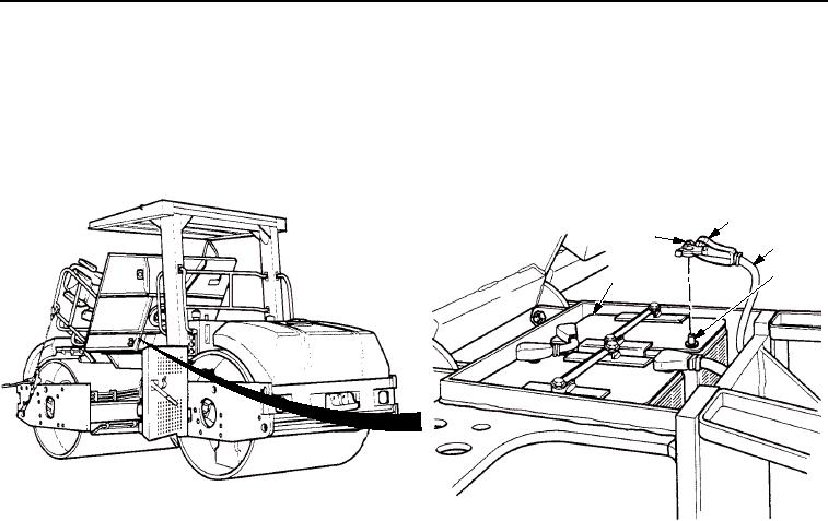
INSTALLATION - Continued
5.
Install cable (Figure 4, Item 4) on negative (-) terminal (Figure 4, Item 5) of battery (Figure 4, Item 1) with nut
(Figure 4, Item 2).
6.
Position battery cable cover (Figure 4, Item 3) over negative (-) terminal (Figure 4, Item 5) of battery
(Figure 4, Item 1).
3
2
4
5
1
M1263SWR
Figure 4. NATO Connector Installation.
END OF TASK
FOLLOW-ON MAINTENANCE
Lower operator platform assembly. (Volume 2, WP 0235)
END OF TASK
END OF WORK PACKAGE
03/15/2011Rel(1.8)root(maintwp)wpno(M00131)