
TM 5-3895-379-23-1
0193
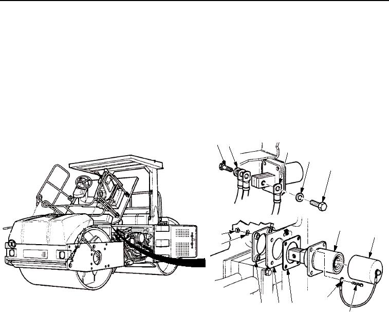
INSTALLATION
1.
Position new gasket (Figure 3, Item 8), NATO connector (Figure 3, Item 4), and insulator (Figure 3, Item 10)
on frame assembly (Figure 3, Item 9).
2.
Install rope clamp (Figure 3, Item 7), four screws (Figure 3, Item 6), washers (Figure 3, Item 11), and new
locknuts (Figure 3, Item 12) to NATO connector (Figure 3, Item 4).
3.
Install three cables (Figure 3, Item 3) on NATO connector (Figure 3, Item 4) with two washers
(Figure 3, Item 2) and screws (Figure 3, Item 1).
4.
Install cap (Figure 3, Item 5) on connector (Figure 3, Item 4).
1
2
3
2
1
4
5
12
11
7
8
10
9
6
M1264SWR
Figure 3.
NATO Connector Installation.
03/15/2011Rel(1.8)root(maintwp)wpno(M00131)