
TM 5-3895-379-23-1
0183
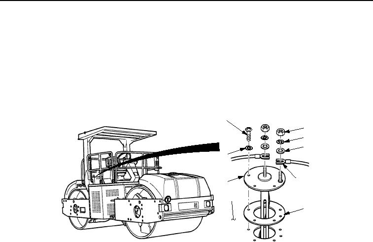
INSTALLATION
NOTE
Fuel level sending unit must be installed so that outside electrical stud is on left-side of roller.
1.
Install new gasket (Figure 2, Item 6) and fuel level sending unit (Figure 2, Item 8) on fuel tank
(Figure 2, Item 7) with five new lockwashers (Figure 2, Item 9) and screws (Figure 2, Item 1).
2.
Install two wires (Figure 2, Item 5) on fuel level sending unit (Figure 2, Item 8) with two washers
(Figure 2, Item 4), new lockwashers (Figure 2, Item 3), and nuts (Figure 2, Item 2).
1
2
3
4
9
5
8
7
6
M1051SWR
Figure 2. Fuel Level Sending Unit Installation.
END OF TASK
FOLLOW-ON MAINTENANCE
Remove chocks. (TM 5-3895-379-10)
END OF TASK
END OF WORK PACKAGE
0183-3/4 blank
03/15/2011Rel(1.8)root(maintwp)wpno(M00121)