
TM 5-3895-379-23-1
0178
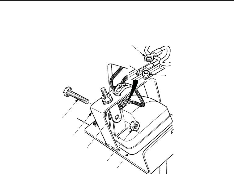
ADJUSTMENT - Continued
2.
To raise or lower beam, loosen nut (Figure 8, Item 4) and reposition work light assembly (Figure 8, Item 3) in
bracket (Figure 8, Item 5). Tighten nut.
1
2
7
6
5
4
3
M1236SWR
Figure 8.
Work Light Adjustment.
3.
Install support (Figure 7, Item 5) in support (Figure 7, Item 3) with two washers (Figure 7, Item 2), screws
(Figure 7, Item 1), washer (Figure 7, Item 2), and screws (Figure 7, Item 4). Tighten screws.
END OF TASK
FOLLOW-ON MAINTENANCE
Remove chocks. (TM 5-3895-379-10)
END OF TASK
END OF WORK PACKAGE
03/15/2011Rel(1.8)root(maintwp)wpno(M00116)