
TM 5-3895-379-23-1
0178
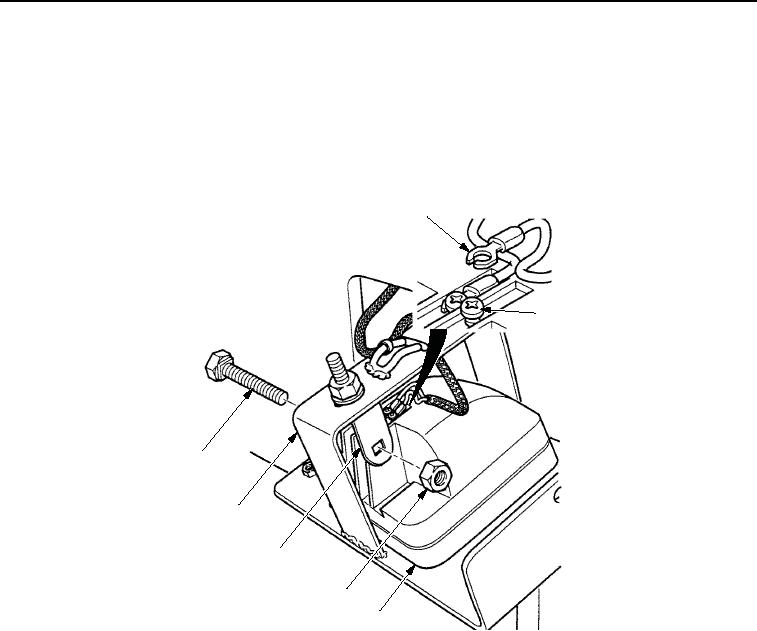
INSTALLATION - Continued
2.
Position work light assembly (Figure 5, Item 3) in support (Figure 5, Item 6).
3.
Position two wires (Figure 5, Item 1) on work light assembly (Figure 5, Item 3) and tighten screws
(Figure 5, Item 2).
4.
Install work light assembly (Figure 5, Item 3) in bracket (Figure 5, Item 5) with screw (Figure 5, Item 7) and nut
(Figure 5, Item 4).
1
2
7
6
5
4
3
M1234SWR
Figure 5.
Work Light Installation.
NOTE
Use cable ties as necessary to attach cables to vehicle.
5.
Install support (Figure 6, Item 5) in support (Figure 6, Item 3) with two washers (Figure 6, Item 2), screws
(Figure 6, Item 1), washer (Figure 6, Item 2), and screw (Figure 6, Item 4). Tighten screws.
03/15/2011Rel(1.8)root(maintwp)wpno(M00116)