
TM 5-3895-379-23-1
0170
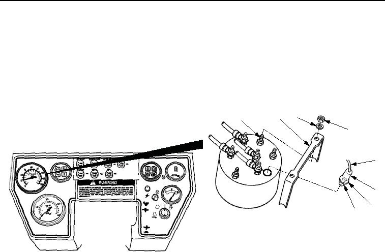
INSTALLATION - Continued
6.
Install two nuts (Figure 8, Item 4), new lockwashers (Figure 8, Item 3), and FPM meter bracket
(Figure 8, Item 2) to FPM meter studs (Figure 8, Item 1).
7.
Install light bulb (Figure 8, Item 8) to light fixture (Figure 8, Item 5). Push and twist bulb clockwise.
8.
Install retainer clip (Figure 8, Item 7) to light fixture (Figure 8, Item 5).
9.
Install light fixtures (Figure 8, Item 5) to FPM meter.
2
3
1
4
5
6
7
8
M0918SWR
STEERING WHEEL SHOWN REMOVED FOR CLARITY
Figure 8. VPM Tachometer and FPM Meter Installation.
10.
Position VPM tachometer (Figure 9, Item 7) in instrument box assembly (Figure 9, Item 9).
11.
Install new lockwasher (Figure 9, Item 6) and wire (Figure 9, Item 5) on VPM tachometer terminal G
(Figure 9, Item 8) with nut (Figure 9, Item 4).
12.
Install new lockwasher (Figure 9, Item 11) and wire (Figure 9, Item 12) on VPM tachometer terminal I
(Figure 9, Item 10) with nut (Figure 9, Item 1).
13.
Install new lockwasher (Figure 9, Item 13) and wire (Figure 9, Item 3) on VPM tachometer terminal S
(Figure 9, Item 14) with nut (Figure 9, Item 2).
03/15/2011Rel(1.8)root(maintwp)wpno(M00108)