
TM 5-3895-379-23-1
0162
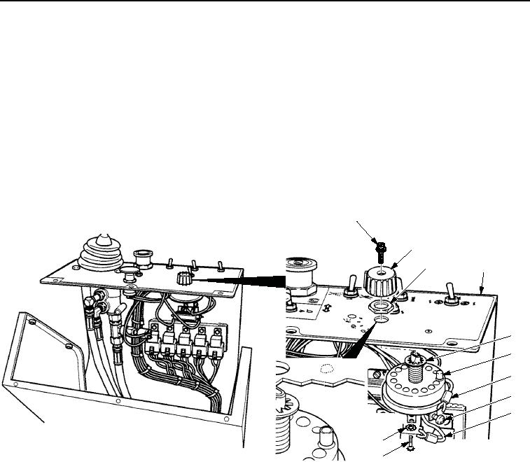
REMOVAL - Continued
NOTE
Tag and mark all wires prior to removal.
4.
Remove screw (Figure 2, Item 10), lockwasher (Figure 2, Item 11), and wire (Figure 2, Item 9) from light switch
(Figure 2, Item 6). Discard lockwasher.
5.
Loosen three screws (Figure 2, Item 8) and remove three wires (Figure 2, Item 7) from light switch
(Figure 2, Item 6).
6.
Remove screw (Figure 2, Item 1) and knob (Figure 2, Item 2) from light switch (Figure 2, Item 6).
7.
Remove nut (Figure 2, Item 3), light switch (Figure 2, Item 6), and lockwasher (Figure 2, Item 5) from panel
assembly (Figure 2, Item 4). Discard lockwasher.
1
2
3
4
5
6
7
8
9
11
10
VIEW FROM DRIVER'S SEAT
M0882SWR
Figure 2. Work Light Control Switch Removal.
END OF TASK
03/15/2011Rel(1.8)root(maintwp)wpno(M00100)