
TM 5-3895-379-23-1
0161
REMOVAL - Continued
NOTE
Tag and mark all wires prior to removal.
5.
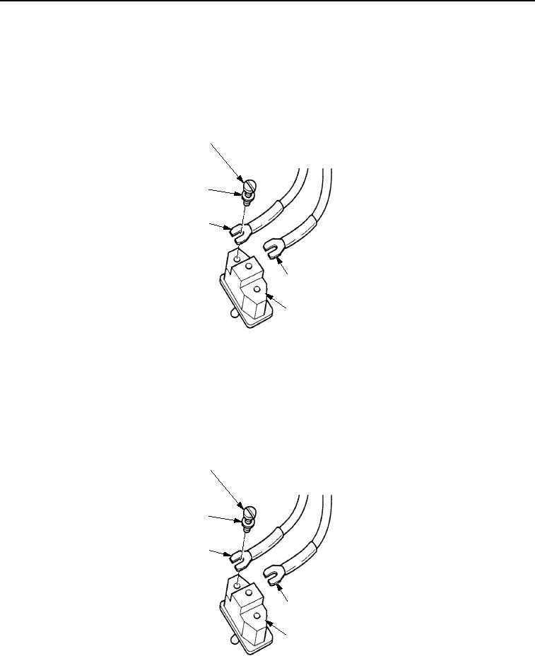
Remove two screws (Figure 3, Item 1), lockwashers (Figure 3, Item 5), and wires (Figure 3, Items 2 and 4)
from propel speed range switch (Figure 3, Item 3). Discard lockwashers.
1
5
4
2
3
M0879SWR
Figure 3. Propel Speed Range Switch Removal.
END OF TASK
INSTALLATION
1.
Install two wires (Figure 4, Items 2 and 4) on propel speed range switch (Figure 4, Item 3) with new lockwashers
(Figure 4, Item 5) and screws (Figure 4, Item 1).
1
5
4
2
3
M1227SWR
Figure 4. Propel Speed Range Switch Installation.
03/15/2011Rel(1.8)root(maintwp)wpno(M00099)