
TM 5-3895-379-23-1
0155
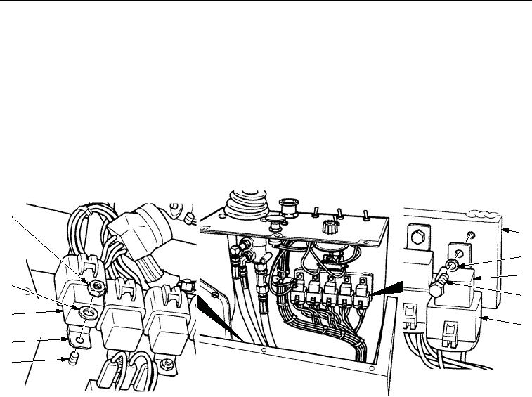
INSTALLATION
NOTE
There are two methods of installing relays. Perform Step (1) or Step (2) as relay requires.
1.
Install relay (Figure 5, Item 4) on operator station (Figure 5, Item 7) with washer (Figure 5, Item 8) and new
locknut (Figure 5, Item 1).
2.
Install relay (Figure 5, Item 4) on panel assembly (Figure 5, Item 2) with washer (Figure 5, Item 3) and screw
(Figure 5, Item 5).
3.
Install connector (Figure 5, Item 6) on relay (Figure 5, Item 4).
1
2
3
4
8
5
6
6
4
7
M1173SWR
Figure 5. Relay Installation.
03/15/2011Rel(1.8)root(maintwp)wpno(M00093)