
TM 5-3895-379-23-1
0150
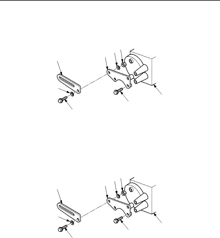
REMOVAL - Continued
3.
Remove locknut (Figure 2, Item 4), washer (Figure 2, Item 3), screw (Figure 2, Item 7), washer
(Figure 2, Item 3), and alternator strap (Figure 2, Item 1) from bracket (Figure 2, Item 2). Discard locknut.
4.
Remove three screws (Figure 2, Item 6) and bracket (Figure 2, Item 2) from engine (Figure 2, Item 5).
4
3
2
1
3
5
6
7
M1065SWR
Figure 2. Alternator Bracket Removal.
END OF TASK
INSTALLATION
1.
Install bracket (Figure 3, Item 2) on engine (Figure 3, Item 5) with three screws (Figure 3, Item 6).
2.
Install alternator strap (Figure 3, Item 1) on bracket (Figure 3, Item 2) with washer (Figure 3, Item 3), screw
(Figure 3, Item 7), washer (Figure 3, Item 3), and new locknut (Figure 3, Item 4).
4
3
2
1
3
5
6
7
M0835SWR
Figure 3. Alternator Bracket Installation.
03/15/2011Rel(1.8)root(maintwp)wpno(M00088)