
TM 5-3895-379-23-1
FIELD MAINTENANCE
ENGINE OIL FILLER REPLACEMENT
INITIAL SETUP:
References
Tools and Special Tools
TM 5-3895-379-23P, Figure 13
Tool Kit, General Mechanic's: Automotive
(Volume 2, WP 0289, Table 1, Item 39)
Equipment Condition
Engine off. (TM 5-3895-379-10)
Materials/Parts
Drums chocked. (TM 5-3895-379-10)
Rag, Wiping
Right-side door assembly opened.
(Volume 2, WP 0288, Table 1, Item 60)
(TM 5-3895-379-10)
Gasket (Volume 2, WP 0290, Table 1, Item 65)
Qty: 2
Personnel Required
Construction Equipment Repairer 91L
REMOVAL
1.
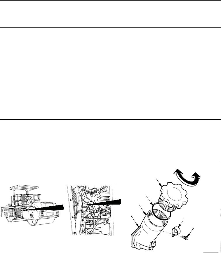
Remove filler cap (Figure 1, Item 1) and seal (Figure 1, Item 6) from filler assembly (Figure 1, Item 5). Inspect
seal and replace if damaged.
2.
Remove screw (Figure 1, Item 3) and clip (Figure 1, Item 2) from bracket (Figure 1, Item 4).
INSTALL
REMOVE
1
6
5
4
2
3
M0115SWR
Figure 1.
Engine Oil Filler Removal.
03/15/2011Rel(1.8)root(maintwp)wpno(M00039)