
TM 5-3895-379-23-1
0078
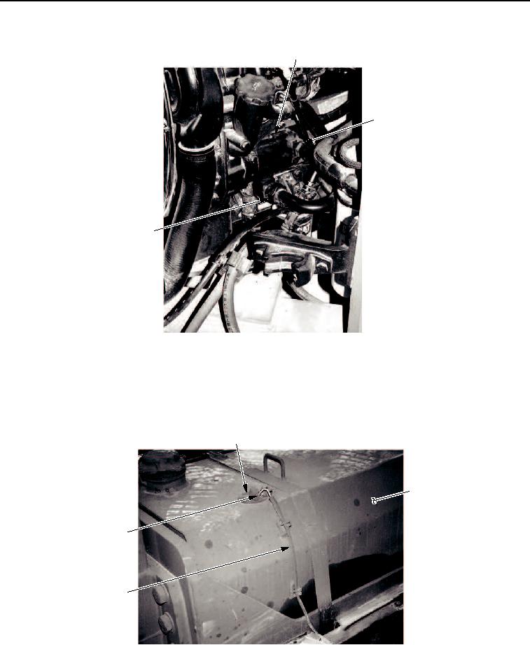
REMOVAL - Continued
1
2
3
M0021SWR
Figure 17. Engine Assembly Removal.
25.
Disconnect electrical wires (Figure 18, Items 4 and 5) from fuel level sending unit (Figure 18, Item 1).
26.
Cut cable ties securing wiring harness (Figure 18, Item 3) to fuel/hydraulic tank (Figure 18, Item 2). Move
harness aside.
1
2
4, 5
3
M0022SWR
Figure 18. Engine Assembly Removal.
03/15/2011Rel(1.8)root(maintwp)wpno(M00017)