
TM 5-3895-379-23-1
0078
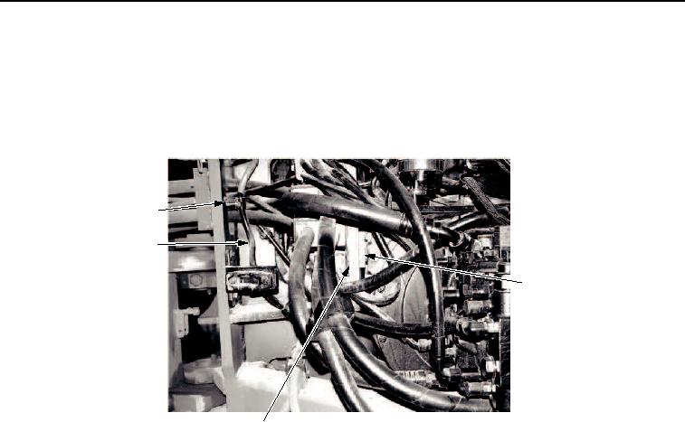
REMOVAL - Continued
22.
Remove two bolts (Figure 16, Item 1), washers (Figure 16, Item 2), clamps (Figure 16, Item 3), and battery
cable (Figure 16, Item 8) from frame. Move cable aside.
23.
Remove two bolts (Figure 16, Item 4), washers (Figure 16, Item 5), and bracket (Figure 16, Item 6) securing
hoses to engine mount (Figure 16, Item 7). Move hoses aside.
1, 2, 3
8
4, 5, 6
7
M0020SWR
Figure 16. Engine Assembly Removal.
24.
Disconnect steering hydraulic hoses (Figure 17, Items 2 and 3) from steering pump (Figure 17, Item 1).
03/15/2011Rel(1.8)root(maintwp)wpno(M00017)