
TM 5-3895-379-23-1
0036
MALFUNCTION
No Power To Functional Light Relay.
CORRECTIVE ACTION
1.
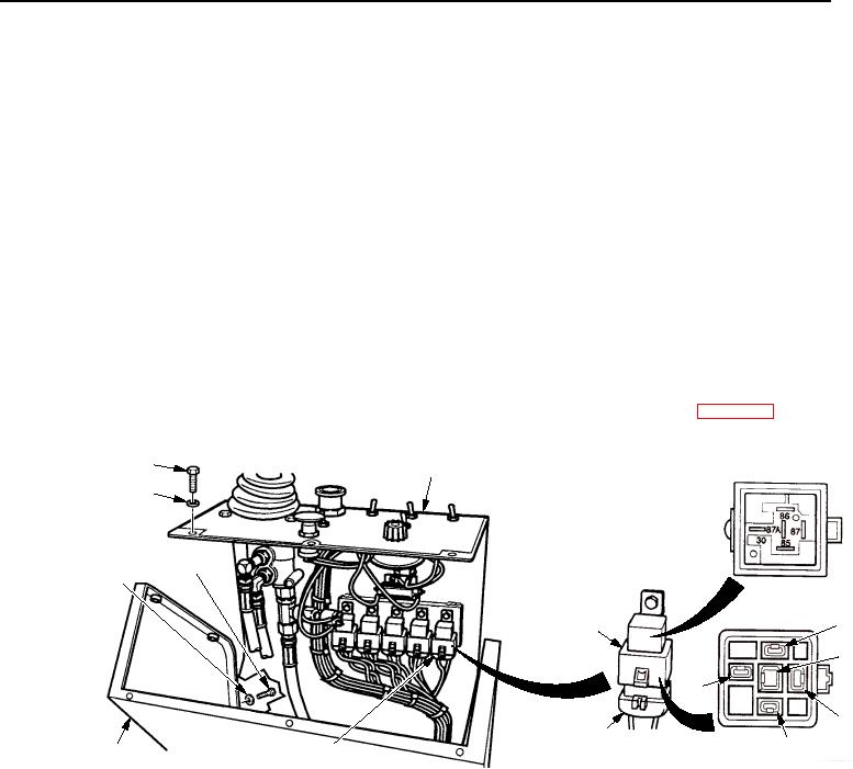
Remove nine screws and washers and remove panel from operating station.
2.
Remove harness connector from functional light relay.
3.
Turn battery disconnect switch to ON position (TM 5-3895-379-10).
4.
Turn engine start switch to ON position (TM 5-3895-379-10).
5.
Touch positive (+) probe of multimeter to terminal 1 (wire 123-WH).
6.
Touch negative (-) probe of multimeter to good ground.
7.
Turn engine start switch to OFF position (TM 5-3895-379-10).
8.
Turn battery disconnect switch to OFF position (TM 5-3895-379-10).
If 24 to 28 VDC are not measured at terminal 1 (wire 123-WH) and GAUGES fuse is good,
repair or replace wire 123-WH and connectors to GAUGES fuse holder (WP 0195).
PANEL
SCREW
ASSEMBLY
WASHER
SCREW
WASHER
2
RELAY
3
1
4
HARNESS
CONNECTOR
5
OPERATOR
FUNCTIONAL
STATION
LIGHT RELAY
T0098SWR
Figure 5. Functional Light Relay Wiring.