
TM 5-3895-379-23-1
0035
MALFUNCTION
Rear Vibration Sensor Faulty.
CORRECTIVE ACTION
1.
Set multimeter to measure VAC.
2.
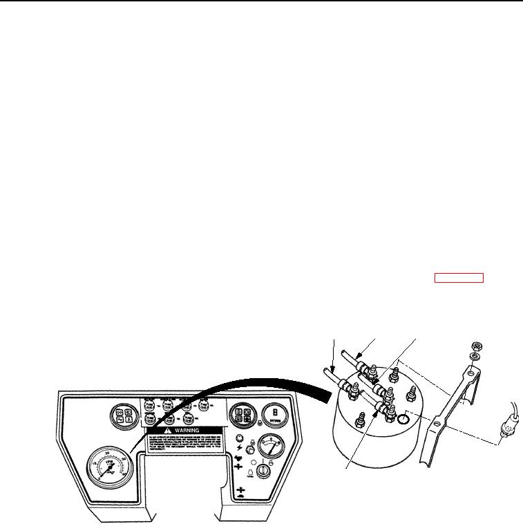
Connect a jumper wire from terminal 1 (black wire) to frame of roller.
3.
Touch positive (+) probe of multimeter to terminal 2 (white wire).
4.
Touch negative (-) probe of multimeter to frame.
5.
Turn battery disconnect switch to ON position (TM 5-3895-379-10).
6.
Have assistant start engine and turn vibratory system on for not more than 10 seconds
(TM 5-3895-379-10).
7.
Multimeter should measure minimum 2.4 VAC peaks.
8.
Have assistant turn engine start switch to OFF position (TM 5-3895-379-10).
9.
Remove jumper wire.
a.
If minimum 2.4 VAC peaks are not measured, replace vibration sensor (WP 0184).
b.
If minimum 2.4 VAC peaks are measured, connect vibration sensor connector to wiring
harness connector. Go to next malfunction.
123-WH
614-PU
200-BK
440-WH
T0119SWR
Figure 2. Vibrator Sensor Wiring.