
DETROIT DIESEL 53
1.7.3 Camshaft Gears
keyway in the gear.
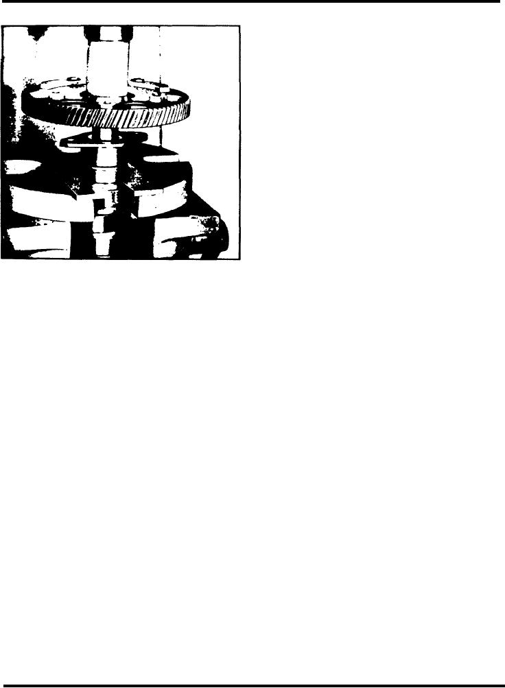
5. Then, with the camshaft supported in an arbor
press, place a sleeve on top of the gear and under the
ram of the press. Bring the ram of the press down on
the sleeve and press the gear tight against the spacer
on the shaft (Fig. 2).
6. Measure the clearance between the camshaft thrust
washer and the camshaft. This clearance should be
.008" to .015" when new parts are used. With used
parts, a maximum clearance of .021" is allowable.
7. Install the gear retaining nut on the camshaft by
hand. Tighten the nut after the shaft is installed in the
cylinder block.
8. Install the gear on the balance shaft in a similar
manner. No rear spacer is used with the balance shaft
gear, since the gear seats against a shoulder on the
shaft.
Fig. 2 lnstalling Camshaft Gear
9. Install the camshaft and balance shaft in the engine
4. Start the camshaft gear over the end of the
as outlined in Section 1.7.
camshaft with the key in the shaft registering with the
Page 2