
DETROIT DIESEL 53
C a m s h a f t and Bearings 1.7.2
the camshaft bore and is used when removing the
end bearing has been `installed Refer to B and C of
other end bearing and any remaining bearings.
Fig. 7.
2. Insert the new intermediate or center bearing into
the camshaft bore and position it correctly Install the
Install Intermediate and/or Center Camshaft
center bearing first.
Bearings
3. Then. with the unthreaded end of shaft J 7593-1
Camshaft center and intermediate bearings must be
started through the pilot. push the shaft through the
installed prior to installing the camshaft end bearings.
entire length of the block bore
On the four cylinder In-Line and 8V engine, the
center. rear intermediate and rear bearings are
4. Slide installer J 7593-6 on the shaft until the
installed in that order by pressing the hearings from
locating pin registers with the notch in the bearing.
the rear to the front of the block. The front
Then, slide installer J 7593-3 or J 7593-15 on the shaft
intermediate and front bearings are installed by
with the large diameter inserted into the end of the
pressing the bearings from the front to the rear of the
block bore. Refer to C and note of Fig. 7.
block. Bearings are similarly installed in the three
cylinder and 6V engine except that there is no center
5. Next, place a spacer (if required). thrust washer.
bearing. The center bearing for the IWO cylinder block
plain washer and hex nut over the threaded end of the
is installed by pressing the bearing from the rear to
puller. The short spacer J 7593-11. shown in Fig. 4. is
the front of the block.
used on the three cylinder (In-Line) and 6Vblocks
The long spacer J 7593-10 is used on the two cylinder
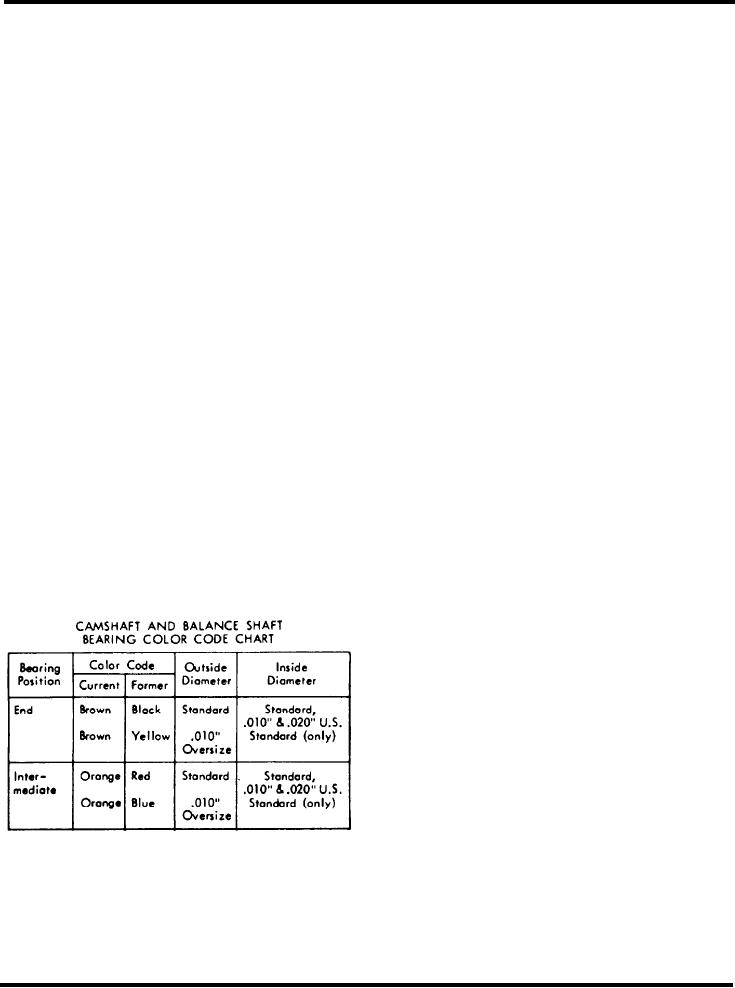
NOTE: Current bearings incorporate lubrication
block.
grooves on the inner bearing surface (Fig. 5).
6. Align the shaft in such a way that a "C" washer.
To properly install the camshaft and balance shaft
J 7593-4. can be inserted in a groove in the shaft
bearings, refer to Fig. 6 for location of the notch in
adjacent to installer J 7593-6.
the bearing in relation to the camshaft or balance
shaft bore centerline in the cylinder block.
7. Place a "C" washer in the groove near the end of
the shaft and, using a suitable wrench on the hex nut,
Also. to facilitate assembly, the camshaft and balance
draw the bearing into place until the "C" washer butts
shaft bearings are color coded on the side and/or end
up against installer J 7593-3 and prevents the shaft
as shown in Table 2.
from further movement.
I. Insert pilot J 7593-2 in the bore of the block as
shown in Fig. 4. Use the small end of the pilot if an
Install End Bearings
Refer to the camshaft and balance shaft color code
chart and the cylinder block bore machining
dimension chart when installing the end bearings.
1. Insert pilot J 7593-2 in the bore of the block as
shown in "D" of Fig. 7. Use the small diameter of the
pilot if a bearing has been installed.
2. Insert support J 7593-12 in the bore in the opposite
end of the block; then, with the unthreaded end of the
shaft started through pilot J 7593-2, push the shaft
through the block and support J 7593-12.
3. Place a new end bearing on installer J 7593-3 and
align the notch in the bearings with the pin on the
installer. Then, slide the installer and the bearing on
the shaft. Position the bearing correctly with the
groove in the camshaft bore.
4. Place "C" washer J 7593-4 in the end notch in the
Table 2
shaft; pull the shaft back until the washer butts
against the installer.
August, 1972
SEC. 1.7.2 Page 5