
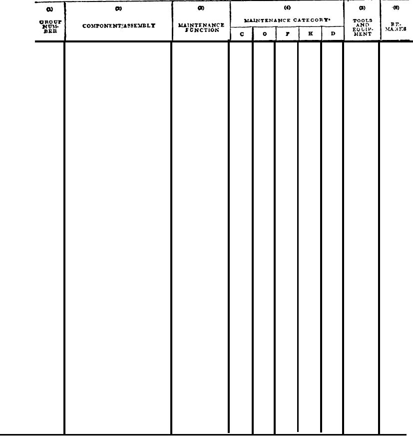
APPENDIX C
Section II. MAINTENANCE ALLOCATION
CHART
ROLLER, PNEUMATIC TIRED, VARIABLE PRESSURE SELF-PROPELLED (CCE)
BODY, HOOD AND
C0WLING
Hood and Cowling
1.0
Replace
1801
1,
2
1.5
Repair
Replace
Heat S h i e l d s
1802
2.0
1,
2
Repair
3.0
Replace
Floor Plates
2.0
1805
1,
2
Repair
3.0
Adjust
Seat
Assembly
0.1
1806
1,
2
Replace
1.0
1.0
Repair
0.5
Replace
Tool Box
1808
1,
2
Repair
0.5
T I R E INFLATION
43
SYSTEM
2.0
Replace
1,
2
4315
4.0
Repair
1
Replace
1.0
Hoses, Lines and
4316
Repair
2.0
Fittings
1.0
Replace
Air Pressure
1,
2
4317
10
Repair
Regulating Valve
Test
0.5
Air Pressure Gauge
Replace
1.0
Replace
1.0
Quick Release Valve
1.0
Repair
1.0
Replace
Pressure Holding
1.0
Repair
Valve
Adjust
0.5
Tire Safety Valve
Replace
0.5
*The subcolumns are as follows:
C-operator/crew
21
O-organizational
F-direct support
H-general support
D--depot