
APPENDIX C
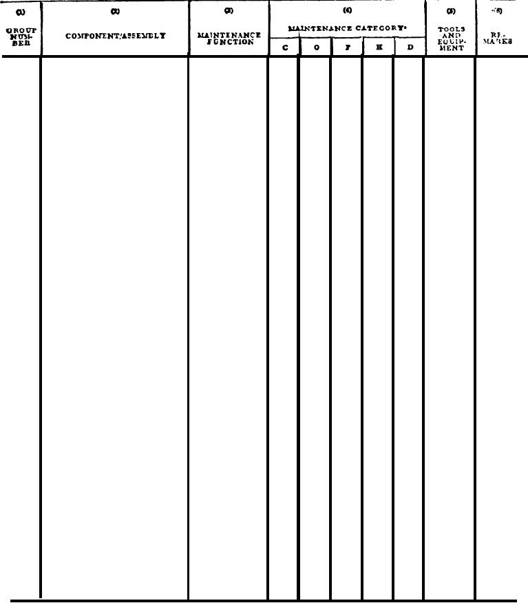
Section II. MAINTENANCE ALLOCATION CHART
ROLLER, PNEUMATIC TIRED, VARIABLE PRESSURE SELF-PROPELLED (CCE)
Replace
Lines and Fittings
2.0
Repair
1.0
WHEELS
13
Inspect
Wheel Assembly
1311
1
0.5
Replace
1.0
Adjust
Hub, Bearings,
0.5
Seal s
Replace
1.0
1
InSpect
Tires
0.2
1313
Replace
1.0
Repair
1.0
STEERING.
14
Steering Wheel
1401
Replace
1
1.0
Service
Center Point Hitch
1405
1,
2
0.5
Replace
3.0
Repair
3.0
Replace
Steering Control
2.0
1407
1,
2
Repair
Unit
2.0
Replace
Hydraulic: Steering
1410
2.0
1,
2
Repair
2.0
Overhaul
4.0
Replace
1411
Hoses, Lines and
1,
2
Repair
Fittings
Replace
1412
Hydraulic Steering
1.0
1,
2
Repair
2.0
Cylinders
Replace
Flow Divider
1.0
1414
1,
2
1.0
Repair
FRAME
15
2
Repair
Frame Assembly
4.0
1501
*The subcolumns are as follows:
C-operator/crew
20
O-organizational
F-direct support
H-general support
D-depot