
SECTION 11
WATER SPRAY SYSTEM
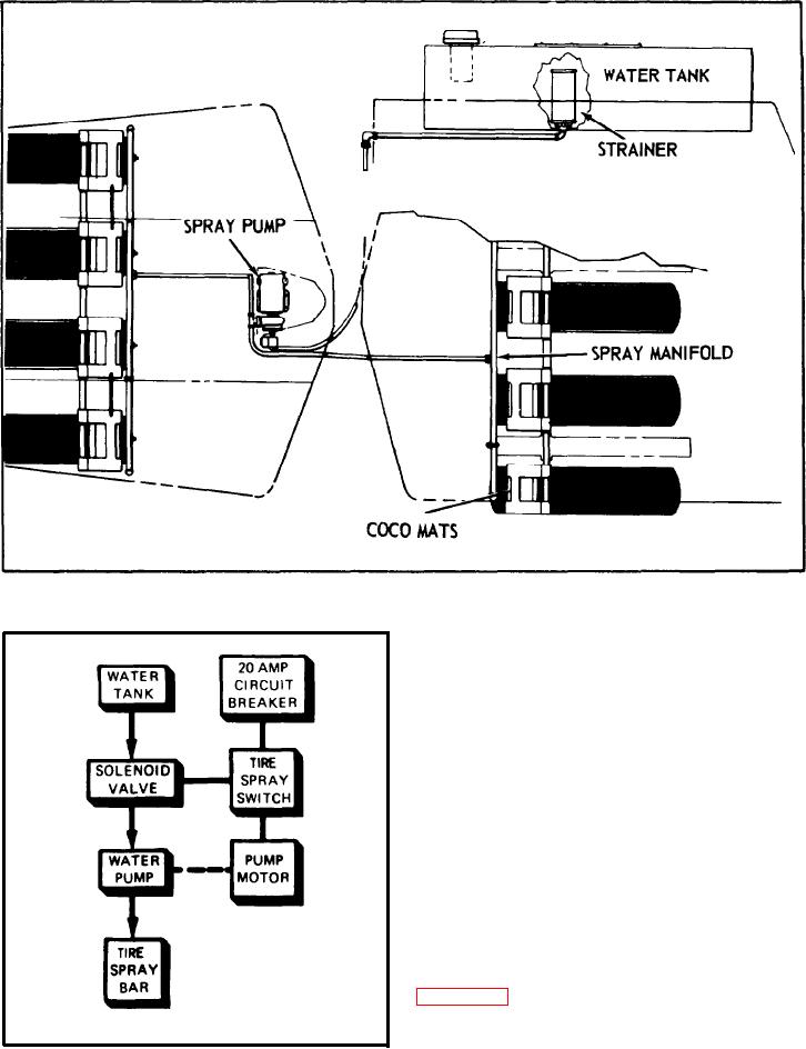
FIGURE 11-2. PRESSURE WATER SPRAY SYSTEM.
11-14. MAINTENANCE.
11-15. The Inlet end sump strainers should be
cleaned as often as necessary to assure an
unrestricted flow of water to the pump. Local
conditions and water source determine the
service schedule.
NOTE: To prevent water draining from the
tank, close the manual valve. Make
sure the manual valve Is open before
spraying Is attempted.
11-16. PUMP AND MOTOR.
11-17. GENERAL.
11-18. Located directly below the floor plate
are the water spray pump and motor (see
1 1 - 1 9 . The pump and motor Is a single
assembly, combining an electric motor with a
FIGURE 11-3.
small Impeller type pump.
11-2.