
SECTION 10
BRAKES AND REAR WHEEL ASSEMBLY
e. If the bushings have to be replaced, drive
a. Remove the spring, pin and pivot block
them out with a round and hammer (see figure
from the wheel support bracket (see figure
10-49. CLEANING AND INSPECTION.
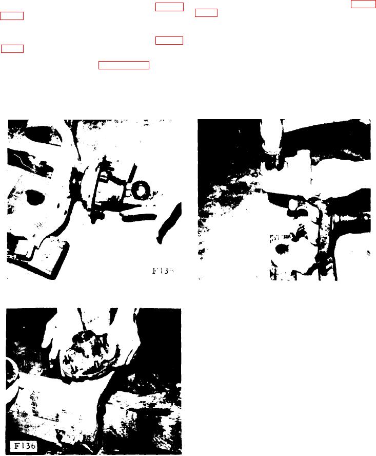
b. Remove the grease cap, locknut, washer
and outer bearing from the axle (see figure
a. Clean all parts in solvent or denatured
alcohol.
c. Remove the hub (see figure 10-14).
b. Inspect the bearings and races for wear,
nicks and burrs. Replace bearings if necessary.
d. Remove the inner bearing and the grease
seal.
FIGURE 10-15.
FIGURE 10-13.
10-50. REASSEMBLY.
a. Pack the inner bearing and install it in the
hub.
b. Install the grease seal in the hub.
c. Slide the hub over the axle.
d. Pack the outer bearing and install it and
the washer and locknut. Bend the cotter pin.
CENTER WHEEL BEARING
10-51.
ADJUSTMENT.
a. `Torque locknut to 150 ft.-lbs. (20.73 kg-m)
while rotating wheel hub. Back off locknut
until wheel hub turns freely with no end play.
Torque on locknut at this point should be less
than 20 ft.-lbs. (2.76 kg-m). Retorque to 25
FIGURE 10-14.
ft.-lbs. (3.46 kg-m) and turn to next position
where cotter pin can be installed.
10-8.