
TM 5-3895-346-14
HYDROSTATIC SYSTEM
PUMP REPAIR
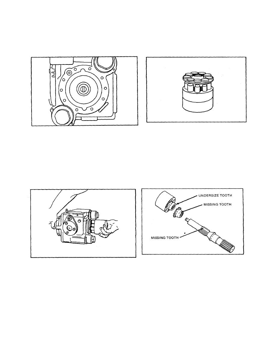
Turn the unit on its side with the large control cavity on top and install the thrust plate. Lubricate the thrust
plate with clean hydraulic oil prior to assembly (refer to Fig. 52).
Figure 52.
Figure 53.
The cylinder block assembly should be installed next. It is necessary to check the alignment of certain parts.
There is no special relationship of pistons, bores, springs, etc. ; however, the alignment of the ball guide and
cylinder block splines is critical. The undersized tooth in the spline of the cylinder block must line up with the
missing tooth in the ball guide spline (refer to Fig. 53).
These in turn line up with a missing tooth on the shaft spline. The hole for the bearing plate locating pin in the
cylinder block face is in line with the undersize tooth in the cylinder block and provides an assembly guide
(refer to Fig. 54 and 55).
Figure 54.
Figure 55.
Lubricate the thrust plate, slippers, pistons, and bores with clean hydraulic oil. Hold the shaft on the external
end, align the missing tooth of the shaft and ball guide sighting through the control cavity and using the locating
pin hole as a guide. Slide the cylinder block assembly onto the shaft and against the thrust plate.
548
