
TM 5-3895-346-14
ENGINE OVERHAUL
FUEL INJECTOR
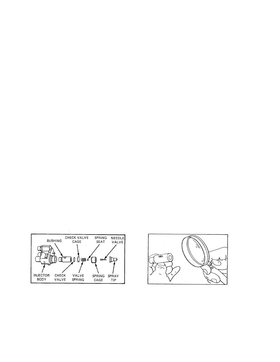
Fig. 32, for even the slightest imperfections will prevent the injector from operating properly. Check for burrs,
nicks, erosion, cracks, chipping, and excessive wear. Also check for enlarged orifices in the spray tip. Replace
damaged or excessively worn parts. Check the minimum thickness of the lapped parts as noted in the chart.
Examine the seating area of the needle valve for wear or damage. Also examine the needle quill and its
contact point with the valve spring seat. Replace damaged or excessively worn parts.
Examine the needle valve seat area in the spray tip for foreign material. The smallest particle of such material
can prevent the needle valve from seat- ing properly. Polish the seat area with polishing stick J 22964. Coat
only the tapered end of the stick with polishing compound J 23038 and insert it directly into the center of the
spray tip until it bottoms. Rotate the stick 6 to 12 times, applying a light pressure with the thumb and forefinger.
CAUTION
Be sure that no compound is accidentally placed on the lapped surfaces located higher up in the spray tip. The
slightest lapping action on these surfaces can alter the near-perfect fit between the needle valve and tip.
Before reinstalling used injector parts, lap all of the sealing surfaces indicated by the arrows in Fig. 31. It is
also good practice to lightly lap the sealing surfaces of new injector parts which may become burred or nicked
during handling.
NOTE
The sealing surface of current spray tips is precision lapped by a new process which leaves the surface with a
dull satin-like finish; the lapped surface on former spray tips was bright and shiny (Fig. 34). It is not
recommended or necessary to lap the surface of a new current spray tip.
Lapping Injector Parts
Lap the sealing surfaces indicated in Fig. 31 and Table 1 as follows:
1. Clean lapping blocks J 22090 with compressed air. Do not use a cloth or any other material for this
purpose.
2. Spread a good quality 600-grit dry lapping powder on one of the lapping blocks.
Figure 31. Sealing Surfaces which may Require
Figure 32. Examining Sealing Surfaces with a
Lapping
Magnifying Glass
231
