TM 5-3895-346-14
CRANKSHAFT
ENGINE OVERHAUL
c.
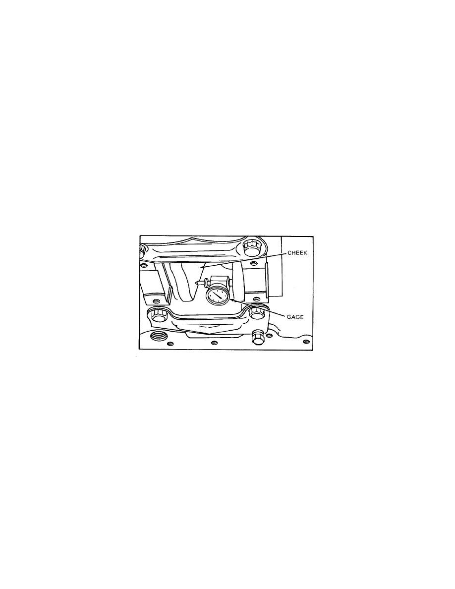
Install a gage (Starrett Co. No. 696 dial gage, or equivalent) in the center punch holes in the cheek
of each counterweight as shown in Fig. 10.
d.
Set the dial indicator at zero, then rotate the crankshaft approximately 90 in both directions. Do
not allow the gage to contact the connecting rod caps or bolts. Note and record the dial indicator readings at the
3, 6, and 9 o'clock crankshaft counterweight positions. The maximum allowable variation is 0.0045-inch total
indicator reading.
NOTE
Remove the tool that was used to rotate the crankshaft when taking the dial
indicator readings.
e.
If the reading on the gage exceeds 0.0045 inch, check the trans- mission, for improper installation
and realign as necessary.
16.
Affix a new gasket to the oil pan flange and install the oil pan.
17. Use a chain hoist and sling attached to the lifting bracket at each end of the engine and remove the
engine from the overhaul stand.
Figure 10. Crankshaft Distortion Measuring Gage Mounted on Crankshaft
18.
Install all of the accessories that were removed.
19. After the engine has been completely reassembled, refer to the Lubricating Oil Specifications and
refill the crankcase to the proper level on the dipstick.
20.
Close all of the drains and fill the cooling system.
21. After replacing the main or connecting rod bearings or installing a new or reground crankshaft,
operate the engine as outlined in Run-In.
114


