TM 5-3895-383-24
7.
Put alignment marks on rear cover plate (4) and housing
(2) for assembly purposes.
8.
Remove six bolts (5), and rem ove rear cover plate (4)
from housing (2).
9.
Remove O-ring seal (3) from housing (2). Check the
O-ring seal for wear or damage and replace if
necessary.
10.
Remove dowel pin (113) from the rear cover plate.
11.
Remove the control plate from the end of rotating group
(1). The control plate is serviced as part of the rotating
group.
12.
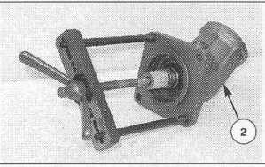
Attach Tooling (B) to housing (2) and rotating group (1)
as shown.
13.
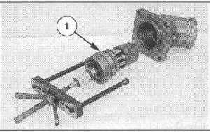
Use Tooling (B) to remove rotating group (1) from the
housing. Make sure the cylinder barrel does not bind as
it is pulled through the housing.
14.
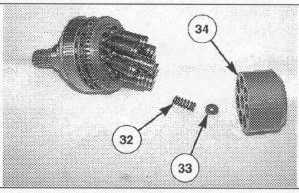
Remove cylinder barrel (34), spacer (33) and spring (32)
from the rotating group. The cylinder barrel spacer and
spring are serviced as part of the rotating group.
15.
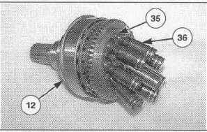
Remove screws (35), and remove pistons (36) and the
retaining plate from shaft assembly (12). The screws,
pistons and retaining plate are serviced as part of the
rotating group. The shaft assembly is serviced
separately.
NOTE: The following steps are for assembly of the
vibratory motor.
NOTE: All motor components must be cleaned and
inspected before assembly. If any components
am worn beyond recommended limits they must
be replaced. Lubricate all moving parts with clean
hydraulic oil during assembly. Assemble the
motor with all new seals.
16.
Apply 9S-3263 Thread Lock on screws (35). Position
the retaining plate and pistons (36) on shaft assembly
(12), and install screws (35).
17.
Install spacer (33) and spring (32) in the center pin bore
of cylinder barrel (34).
18.
Install the cylinder barrel on the pistons and center pin.
14-123


