TM 5-3895-383-24
The steering system is a load sensing system. Hydraulic oil for
the steering circuit is supplied by the gear pump (2). The
priority valve (7) gives priority to the steering circuit. The
priority valve senses pressure in the steering circuit. Then, the
priority valve directs flow to the metering pump (5). The
amount of oil flow depends on rotation of the steering wheel by
the operator. When the steering wheel is not being turned, the
priority valve shifts and the oil flow is directed away from the
steering circuit.
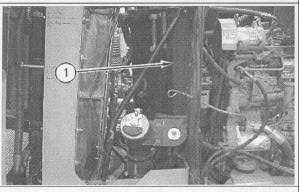
Illustration 12
Left Side of Machine
(1) Hydraulic oil tank
Hydraulic oil tank (1) is located to the rear of the engine. A
strainer is located in the hydraulic oil tank. The hydraulic oil
passes through the strainer and the oil goes to the suction side
of the metering pump.
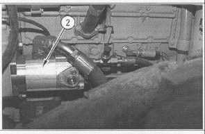
Illustration 13
Left Side of Machine
(2) Gear pump.
The gear pump (2) is located in the engine compartment The
gear pump is driven by the engine. Suction is from the
hydraulic oil tank (1). The gear pump provides oil flow for the
steering circuit, the charge circuit the fan motor, and the
leveling blade (if equipped).
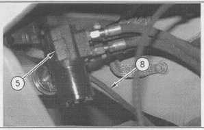
Illustration 14
Located Under the Operators Platform
(5) Steering metering pump. (8) Load sensing line.
The oil flows from the gear pump (2) to metering pump (5).
The metering pump is located at the bottom of the steering
column under the console. The metering pump is load
sensing. The load sensing line (8) provides the pilot signal to
the gear pump.
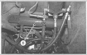
Illustration 15
Location of Metering Pump
(6) Steering cylinder
When the steering wheel is turned, two double acting steering
cylinders (6) receive oil from the metering pump (5) in order for
the compactor to make the desired turn. When the steering
wheel is not being turned, a small amount of oil is required in
order to provide a dynamic signal for fast steering response.
With the steering control valve spool in the spring centered
position, oil is blocked to the steer cylinders.
12-15