TM 5-3895-383-24
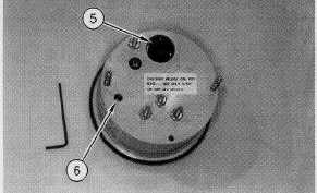
Illustration 75
(5) Dial. (6) Small calibration screw.
7.
Set large dial (5) on 8.
8.
Use small calibration screw (6) in order to calibrate the
gauge. Use a 2.0 mm (5/64 inch) allen wrench in order
to adjust the small calibration screw.
NOTE:
If the reading from VPM gauge (3) is significantly
different from the reading for 133-0963 Drum
Vibration
Tachometer
(4)
or
the
133-9905
Frequency Meter, the magnetic sensor output
should be verified before tachometer (3) is
calibrated.
Vibratory Magnetic Sensor - Test and Adjust
SMCS Code: 6606-025-NS; 6606-081-NS
Personal injury or death can result from sudden machine
movement.
Sudden movement of the machine can cause injury to
persons on or near the machine.
To prevent injury or death, make sure that the area around
the machine is clear of personnel and obstructions before
operating the machine.
NOTICE
To avoid damage to the vibratory system during testing,
always perform the testing with the vibratory drum on top
of tires or on loose dirt. Tires will simulate a non-
compacted soil condition.
Never operate the vibratory system when the machine is
on concrete.
NOTICE
If a testing time longer than three (3) minutes is required,
rotate the drum periodically in order to lubricate the
eccentric weight shaft bearings.
Table 17
Tools Needed
6V-7070
Digital Multimeter (or equivalent)
1
NOTE:
The hydraulic oil temperature should be at least
38° C (100° F).
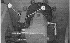
Illustration 76
Right Side Of Drum As Viewed From Operator Seat
(1) Guard. (2) Magnetic sensor.
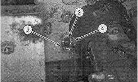
Illustration 77
Vibratory Magnetic Sensor Location
(2) Magnetic sensor. (3) Wires. (4) Case.
1.
Remove guard (1) from top of magnetic sensor (2).
2.
Remove rubber boot. Disconnect two wires (3) from
magnetic sensor (2).
11-64


