TM 5-3895-383-24
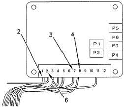
Illustration 67
Variable Frequency Controller
(2) Wire terminal 1. (3) Wire terminal 7. (4) Wire terminal 8.
(6) Frame ground wire terminal 2.
1.
Apply the parking brake. Place the propel control lever
in the STOP position. Put the vibratory control switch
on the propel control lever in the OFF position.
2.
Remove the cover from the operator console in order to
access variable frequency controller (1).
3.
Turn the key start switch to the ON position. Do not
start the engine.
4.
Use 6V-7070 Digital Multimeter in order to check the
input voltage between wire terminal 1 (2) and frame
ground wire terminal 2 (6). The input voltage should be
a minimum of 24 DCV.
5.
Use the multimeter to check the reference voltage
between wire terminal 7 (3) and frame ground wire
terminal 2 (6) on the variable frequency controller. The
voltage should be 5.1 DCV.
6.
Use the multimeter to check the reference voltage
between wire terminal 8 (4) and frame ground wire
terminal 2 (6) on the variable frequency controller. The
voltage should be 2.55 DCV.
7.
If the reference voltage that is measured at wire terminal
7 (3) and 8 (4) is not correct, and there is a minimum of
24 DCV at wire terminal 1 (2), then a problem exists
with the voltage regulator for the variable frequency
controller.
If the reference voltages that are measured at wire terminals 7
(3) and 8 (4) are correct, and there is a minimum of 24 DCV at
wire terminal 1 (2), then perform Testing and Adjusting
Controller in the section that follows.
11-59


