TM 5-3895-383-24
2.
Make sure that the manual directional control valve (4)
is in the neutral position.
3.
Disconnect electrical connector (2) for the neutral start
switch (1).
4.
Clip the multimeter leads to the two pins in the electrical
connector (2). Switch the multimeter to the position that
will measure continuity.
5.
Loosen locknut (5) that is holding the neutral start
switch.
6.
Turn the neutral start switch until the beep from the
multimeter cannot be heard. Turn the switch in the
counterclockwise direction until the beep is heard.
7.
Hold the neutral start switch and tighten the locknut.
Charge Relief Valve - Test and
Adjust
SMCS Code: 5117-025-PX; 5117-081-PX
Table 13
Required Tools
Part Number
Description
Quantity
8T-0855
Pressure Gauge
4000 kPa
(580 psi)
1
Personal injury or death can result from sudden machine
movement.
Sudden movement of the machine can cause injury to
persons on or near the machine.
To prevent injury or death, make sure that the area around
the machine is clear of personnel and obstructions before
operating the machine.
Personal injury can result from hydraulic oil pressure and
hot oil.
Hydraulic oil pressure can remain in the hydraulic system
after the engine has been stopped. Serious injury can be
caused if this pressure is not released before any service
is done on the hydraulic system.
Make sure all of the attachments have been lowered, oil is
cool before removing any components or lines. Remove
the oil filler cap only when the engine is stopped, and the
filler cap is cool enough to touch with your bare hand.
NOTICE
Care must be taken to ensure that fluids are contained
during performance of inspection, maintenance, testing,
adjusting and repair of the product. Be prepared to collect
the fluid with suitable containers before opening any
compartment or disassembling any component containing
fluids.
Refer to Special Publication, NENG2500, "Caterpillar Tools
and Shop Products Guide" for tools and supplies suitable
to collect and contain fluids on Caterpillar products.
Dispose of all fluids according to local regulations and
mandates.
NOTE:
A charge relief valve is located in both the propel
pumps. The charge relief valve in the drum propel
pump should be the controlling relief valve (lower
pressure setting). If the setting for the drum
charge relief valve does not change, the axle
charge relief valve may be set too low.
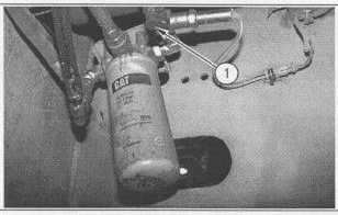
Illustration 71
Charge Pressure Test
(1) Charge pressure test port.
10-68