TM 5-3895-383-24
Check the following parameters if the travel speed is not
correct.
1.
Pump efficiency.
2.
Charge relief valve setting.
3.
Check the main relief valve setting.
4.
Make sure that the machine is in the HIGH SPEED
range.
5.
Make sure that the linkage rod between the propel
pumps is adjusted correctly.
6.
Check the axle propel motor for the correct minimum
displacement adjustment.
Piston Pump Relief Valve
(Axle Propel and Drum Propel) -
Test and Adjust
SMCS Code: 3203-025-PV; 3203-081-PV
Table 8
Required Tools
Part number
Description
Quantity
8T-0861
Pressure Gauge
1
60000 kPa
(8700 psi)
Personal injury or death can result from sudden, machine
movement.
Sudden movement of the machine can cause injury to
persons on or near the machine.
To prevent injury or death, make sure that the area around
the machine is clear of personnel and obstructions before
operating the machine.
Escaping fluid under pressure, even a pinhole size leak,
can penetrate body tissue, causing serious injury, and
possible death. If fluid is injected into your skin, it must
be treated immediately by a doctor familiar with this type
of injury.
Always use a board or cardboard when checking for a
leak.
NOTICE
Care must be taken to ensure that fluids are contained
during performance of inspection, maintenance, testing,
adjusting and repair of the product. Be prepared to collect
the fluid with suitable containers before opening any
compartment or disassembling any component containing
fluids.
Refer to Special Publication, NENG2500, “Caterpillar Tools
and Shop Products Guide” for tools and supplies suitable
to collect and contain fluids on Caterpillar products.
Dispose of all fluids according to local regulations and
mandates.
NOTE:
Follow the same test procedure and the same
adjustment procedure for the relief valves on the
axle propel pump and the drum propel pump.
Before you conduct the test procedure on the main relief
valves, the following steps must be followed:
Place the propel control lever in NEUTRAL position.
Place the machine in position against a solid, stationary
object such as a loading dock. The wheels may be
blocked and the drum may be blocked instead of placing
the machine against a stationary object.
Make sure that the parking brake is applied.
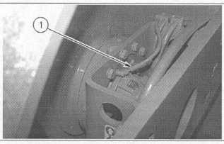
Illustration 63
Drum Dive Motor
(1) Brake line.
1.
Remove brake line (1) from the drum drive motor. Plug
the brake line and cap the fittings.
10-63