TM 5-3895-383-24
The fuel injection pump (unit injector) allows a small amount of
fuel to be injected at the proper time into the combustion
chamber. The fuel is supplied by fuel gallery (10) around each
injector. Each of these galleries is connected by a drilled
passage in the cylinder head. This passage provides a
continuous flow of fuel to all unit injectors.
The unit injector is isolated from the coolant passage by sleeve
(11). This sleeve also provides the seating surface for the
injector.
Injection timing is determined by the angular location of cam
(14) and the vertical location of plunger (6) in barrel (9). The
angular location of the cam is controlled by the camshaft to
crankshaft gear mesh at the front of the engine. The location
of the plunger (fuel timing) is adjusted by setscrew (2).
As the camshaft rotates, its profile is sent to rocker arm (1) by
lifter (13) and push rod (5). The motion of rocker arm (1) is
then sent to plunger (6) through the floating button (3).
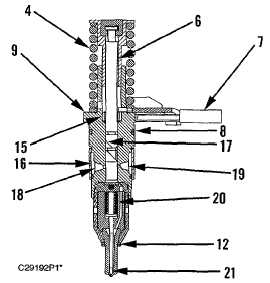
Fuel Injector Pump (Unit Injector)
(4) Tappet spring. (6) Plunger. (7) Rack. (8) O-ring. (9)
Barrel. (12) O-ring. (15) Gear. (16) Sleeve filter. (17) Helix.
(18) Lower port. (19) Upper port. (20) Spring. (21) Check
(needle valve).
At the top of the plunger's stroke, fuel from fuel gallery (10)
enters the injector around the edges of sleeve filter (16). The
fuel then fills the volume below plunger (6).
During the plunger's downward motion, fuel beneath the
plunger is displaced into the gallery through the two ports in
barrel (9). As upper port (19) is closed by the bottom edge of
the plunger, fuel continues to be displaced through lower port
(18). When the lower port is closed, effective stroke begins
and the fuel inside the injector becomes pressurized by the
continued downward movement of the plunger. When the fuel
pressure is sufficient to open check (21), high pressure fuel will
be forced through the orifices at the bottom of the nozzle into
the combustion chamber. This will continue until upper port
(19) is uncovered by helix (17) on the plunger. At this instant,
effective stroke ends and this high pressure fuel will spill
through upper port (19) into the gallery allowing spring (20) to
close check (21). This will end the injection cycle.
The plunger will continue its downward movement until the liter
(13) reaches the nose of the cam. Then the plunger will be
returned upward by tappet spring (4) causing the cavity under
the plunger to be refilled from the fuel in the gallery. Now the
injector is ready for the next cycle.
In addition to vertical motion, the plunger can rotate with
respect to barrel (9) by gear (15). This gear, which slides to
allow vertical movement of the plunger, meshes with rack (7).
The rotation of the gear changes the relationship between helix
(17) and upper port (19). The amount of fuel injected into each
combustion chamber then changes. For example, if rack (7) is
moved to the right, plunger (6) rotates CCW (from top). The
distance between the bottom end of the plunger and helix (17)
then increases with respect to upper port (19). Thus the
effective stroke is increased and more fuel is injected into the
combustion chamber.
6-10