TM 5-3895-382-24
Swashplate Neutral Adjustment Procedure
(9XL229-Up, 3WZ158-Up, 2JM579-Up, 4JZ122-Up, 3TM706-
Up, 5BZ119-Up, 6EN127-Up, 2TN118-Up, 1ZN121-Up, 1FS1-
Up, 1XZ1-Up)
Tools Needed
6V-7830
Tetra Gauges
1
Make
reference
to
WARNING
on
first
page
of
Troubleshooting.
NOTE:
Tests should be performed on tires or loose dirt.
Tires are recommended. Never operate the
vibratory system when the machine is on
concrete.
NOTE:
Make sure the parking brake is applied, and the
propel control lever is in neutral.
Flushing Manifold.
(1) Test port for vibratory high amplitude) pressure. (2) Test port for
vibratory (low amplitude) pressure. (3) Servo port.
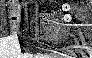
Vibratory Pump.
(4) Servo port. (5) Pump neutral adjustment.
1.
Connect two 60 000 kPa (8700 psi) pressure gauges to
test ports (1) and (2).
2.
Remove plugs from servo ports (3) and (4). Install a
3445 kPa (500 psi) minimum pressure hose between
servo port (3) and servo port (4). This will cross port the
servo and remove the effects of any control pressure on
the servo piston.
3.
Start and slowly accelerate the engine to full throttle.
Operate the vibratory system in both high and low
amplitudes several times and then stop the vibratory
system.
4.
With the servo cross-port line installed, note the system
pressure gauge readings with engine running at low
idle. The difference in the system pressure gauge
readings is the offset pressure.
NOTE:
To achieve finer gauge resolution, lower pressure
gauges will be required. 60 000 kPa (8700 psi)
pressure gauges are used at the beginning to
prevent gauge damage.
5.
If the offset pressure is not zero, loosen the pump
neutral adjustment locknut with a 17 mm hex wrench.
Turn the pump neutral adjustment screw (5) with a 7
mm hex wrench until the system pressure gauge
readings are equal.
6.
Turn the pump neutral adjustment screw (5) clockwise
until one of the gauges registers an increase in system
pressure. Note the position of the pump neutral
adjustment screw (5).
7.
Turn
the
pump
neutral
adjustment
screw
(5)
counterclockwise until the other gauge registers an
increase in system pressure. Note the position of the
pump neutral adjustment screw (5).
8.
Turn the pump neutral adjustment screw (5) to a
position halfway between the positions noted above.
The system pressure gauges should indicate equal
pressures.
9.
Once the swashplate neutral has been found, hold the
servo adjustment screw from turning and torque the
pump neutral adjustment locknut to 28 to 51 Nm (21 to
37 lb-ft).
10.
Stop the engine. Remove the pressure gauges and
servo cross port line. Reinstall the plugs in the servo
pods (3) and (4).
13-34