TM 5-3895-382-24
VPM Measurement Tests
If the hand held meter is correct and the vpm meter does not
accurately indicate system frequency, check the following
procedures to determine the cause, and repair.
Magnetic Sensor Voltage Test
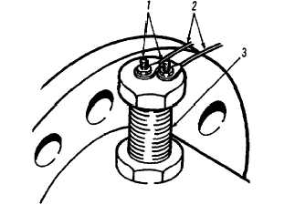
Magnetic Sensor.
(1) Terminals. (2) Wires. (3) Case.
1.
Disconnect two electrical wires (2) from magnetic
sensor.
2.
Set a voltmeter on lowest AC setting. Attach voltmeter
leads to magnetic sensor terminals (1).
3.
Start engine and run at full throttle.
4.
Move vibratory control switch to the low-amplitude
position.
5.
There should be a reading on the voltmeter as the
magnetic sensor picks up pulses from the sprocket as
the drive shaft rotates.
6.
If no reading is obtained, the magnetic sensor may be
out of adjustment, or may need to be replaced.
7.
Shut engine OFF.
Magnetic Sensor Resistance
Magnetic Sensor.
(1) Terminals. (2) Wires. (3) Case.
1.
Disconnect two electrical wires (2) from magnetic
sensor.
2.
Touch the leads of an ohmmeter to terminals (1).
Resistance should be 265 30 ohms. If not, replace
the magnetic sensor.
3.
Set the ohmmeter on its highest setting.
4.
Attach one ohmmeter lead to one of the magnetic
sensor terminals (1). Touch the other ohmmeter lead to
the magnetic sensor case (3).
5.
Electrical resistance should be infinite. If the ohmmeter
gives any reading, the magnetic sensor should be
replaced.
6.
Repeat Steps 4 and 5 for the other terminal (1) of the
magnetic sensor.
13-38


